The Xbee is the brand name a wireless transceiver device which works on the ZigBee protocol. The ZigBee is the name of a wireless protocol maintained by the IEEE 802.15 standard. This is a protocol specified for wireless Personal Area Network (PAN) using low powered wireless transceivers. They can be used for simple point to point communication systems also.
They have an approximate range of 10 to 100 meters and are used in industries, scientific fields, medical fields etc. The Xbee module even though uses complex packet data based Zigbee protocol for communicating with each other, they can communicate with other devices using simplest serial communication protocol and hence they are widely used in microcontroller base boards. This project demonstrates how to interface an Xbee module with the Arduino board and perform a full transmission and reception test between two Xbee modules generally known as loop back test.
Any AVR microcontroller based board which follows the standard Arduino schematic and is flashed with the Arduino bootloader can be called an Arduino board. The Arduino board is built around an AVR microcontroller and it has all the required circuitry to get the built-in AVR microcontroller running. The Arduino IDE is so simple to use that anyone who has basic knowledge of c programming can quickly get started with it. The project on how to get started with the Arduino explains the steps required to get start with an Arduino board.
The Arduino can communicate with the other devices using its digital I/O, serial port, I2C port, SPI port etc. In this project one Xbee is connected to the serial port of the Arduino board and another Xbee is connected to serial monitoring software which can display the received data and also send data to the Xbee module which is connected to the serial port of the PC.
Two Xbee S1 series transceivers modules are used in this project and the image of the same module shown in the following figure. Since the pitch of the pins of the modules are not breadboard compatible one can use the Xbee based design boards which comes with breadboard compatible pins. 
Fig. 2: Xbee S1 Series Transceiver Module
The Xbee modules have several digital and analog I/O pins apart from these pins and the pin out of an Xbee module is shown in the following table:
|
PIN |
DESCRIPTION |
|
1 |
Power Supply |
|
2 |
UART Data Out |
|
3 |
UART Data In |
|
4 |
Digital Output 8 (not supported as of 2/28/09) |
|
5 |
Module Reset (reset pulse must be at least 200 ns) |
|
6 |
PWM Output 0 / RX Signal Strength Indicator |
|
7 |
PWM Output 1 |
|
8 |
Do not connect |
|
9 |
DTR / Pin Sleep Control Line or Digital Input 8 |
|
10 |
Ground |
|
11 |
Analog Input 4 or Digital I/O 4 |
|
12 |
Clear-to-Send Flow Control or Digital I/O 7 |
|
13 |
Module Status Indicator |
|
14 |
Voltage Reference for A/D Inputs |
|
15 |
Associated Indicator, Analog Input 5 or Digital I/O 5 |
|
16 |
Request-to-Send Flow Control, Analog Input 6 or Digital I/O 6 |
|
17 |
Analog Input 3 or Digital I/O 3 |
|
18 |
Analog Input 2 or Digital I/O 2 |
|
19 |
Analog Input 1 or Digital I/O 1 |
|
20 |
Analog Input 0 or Digital I/O 0 |
Fig. 3: Pin Out Of Xbee Module
The Arduino board used in this project is the Arduino pro-mini board and the IDE version of the Arduino is 1.0.3 for windows. The image of the Arduino pro-mini board and the Arduino IDE are shown below:

Fig. 4: Typical Arduino Pro-Mini Board

Fig. 5: Arduino IDE Software Window
Since the arduino pro-mini board has no circuitary for interfacing it with the serial port or the USB port of the PC, an external USB to TTL converter board is required to connect it with the PC. This hardware helps in programming the Arduino board and also helps in the serial communication with the USB port of the PC.

Fig. 6: External USB to TTL converter board for programming Arduino and serial communication
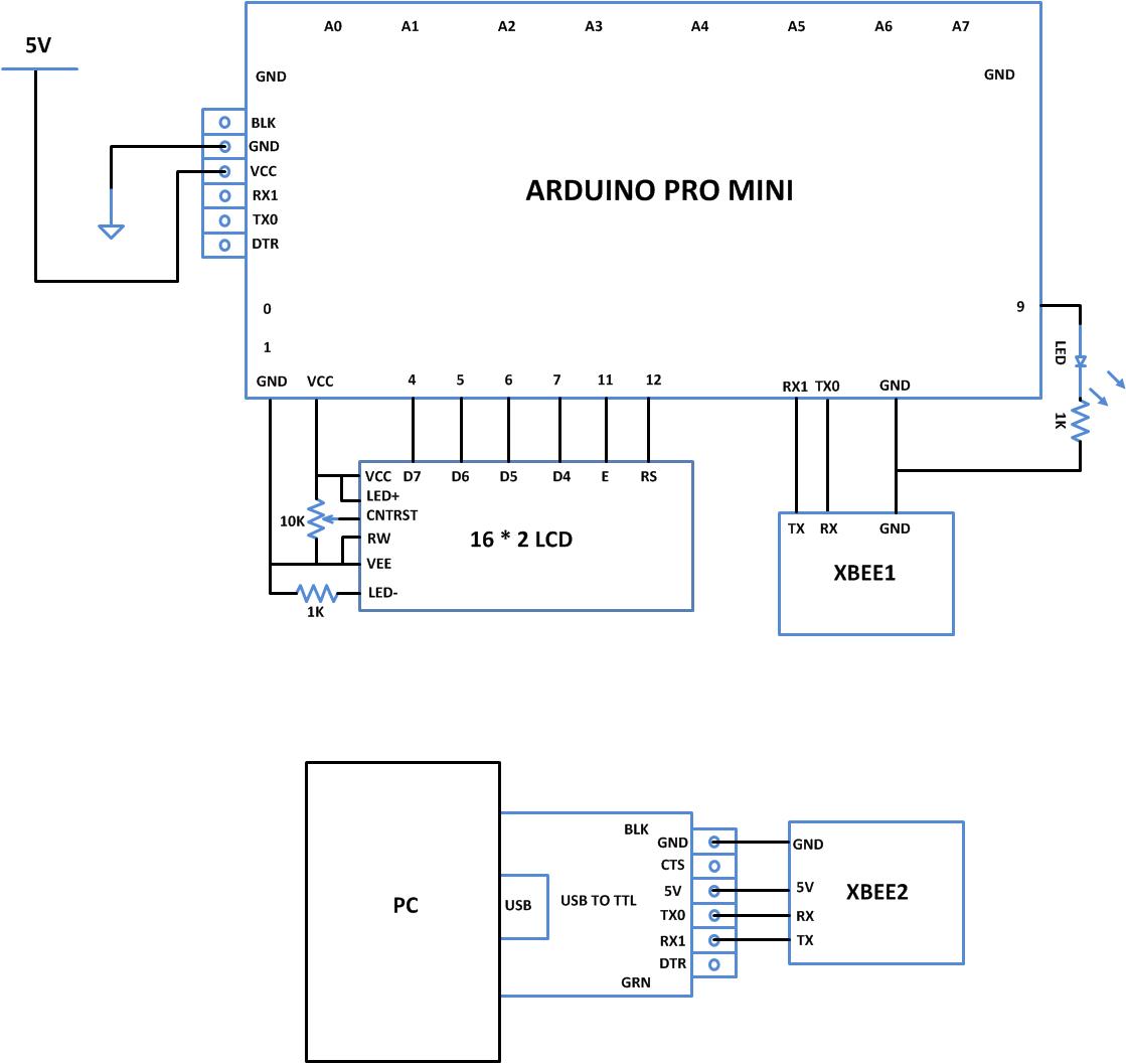
Since the Xbee modules communicate using serial communication protocol with the interfacing devices they can be connected to a microcontroller using a minimum of four pins, Power supply, and Ground, UART Data Out, and UART Data In pins.
The pin number 2, UART Data Out is connected to the RX1 pin of the Arduino pro mini board and pin number 3 UART Data In is connected to the TX0 pin. The code written for this project communicates with the Xbee using the serial communication functions provided by the Arduino library. The functions like Serial.begin() which helps to initialize the serial port with a given baud rate, Serial.write() to send a data to the serial port, Serial.available() and Serial.read() functions to read data from the serial port are used in this project and they are already discussed in previous projects on how to do serial communication with the Arduino, how to send and receive serial data using arduino and how to do serial debugging with the Arduino.
In this project both the Xbee modules has to perform transmission and reception to complete the transmission of a data byte from PC to the Arduino board and back to the PC again. The block diagram below represents the implementation of the entire system.

Fig. 7: Block Diagram Of Loop Back Test On Xbee Connected With Arduino
THE CODE
The loop back testing code makes use of the above mentioned serial communication functions to communicate with the Xbee module. The Arduino board waits till it receives some data from the Xbee module which is connected to the PC through the Xbee connected to it and sends back the same data to the other Xbee module which is connected to the PC. Serial monitoring software is running in the PC side which can monitor and access the serial port where the Xbee is connected so that one can observe the incoming data and also send some data to the serial port where the Xbee is connected. The following text shows how the code will look like;
if(Serial.available()) // wait till a data byte is received
{
inByte = Serial.read(); // get incoming byte:
Serial.write(inByte); // send the same character back to serial port
}
When the coding is finished one can verify and upload the code to the Arduino board as explained in the project how to get started with the Arduino. As soon as the board is powered up the Xbee in the Arduino board automatically establishes communication with another Xbee which is connected to the serial port of a PC. The second Xbee board can be connected to the PC using the same USB to TTL converter board which has been used to program the Arduino board. Now open the serial monitor software and type some text using the keyboard without turning on the ‘local echo’ option and one can observe the same characters appears on the serial monitor window.
Project Source Code
###


/*============================ EG LABS ===================================//


 Demonstration on how to perform loop back test on XBEE with an arduino board


 The circuit:

 LCD:

 * LCD RS pin to digital pin 12

 * LCD Enable pin to digital pin 11

 * LCD D4 pin to digital pin 7

 * LCD D5 pin to digital pin 6

 * LCD D6 pin to digital pin 5

 * LCD D7 pin to digital pin 4

 * LCD R/W pin to ground

 * 10K resistor:

 * ends to +5V and ground

 * wiper to LCD pin 3

 * LED anode attached to digital output 9

 * LED cathode attached to ground through a 1K resistor


 XBEE:

 RX PIN OF XBEE TO TX0 PIN OF ARDUINO

 SHORT THE GROUND PINS OF ARDUINO AND XBEE


============================== EG LABS ===================================*/


#include <LiquidCrystal.h>


// initialize the library with the numbers of the interface pins

LiquidCrystal lcd(12, 11, 7, 6, 5, 4);


// give the pin a name:

int led = 9;

// incoming serial byte

int inByte = 0;


void setup()

{

  // set up the lcd's number of columns and rows:

  lcd.begin(16, 2);

  lcd.print("ENGINEERS GARAGE");

  lcd.setCursor(0, 1);

  lcd.print("   XBEE + GPS   ");


  // initialize the led pin as an output.

  pinMode(led, OUTPUT);

  // start serial port at 9600 bps

  Serial.begin(9600);

  // wait for a while till the serial port is ready

  delay(100);


// send the initial data once //

  Serial.print('n');

  Serial.print("      EG LABS   ");

  Serial.print('n');

  Serial.print('r');

  Serial.print(" XBEE LOOP BACK TEST");

  Serial.print('n');

  Serial.print('r');

  Serial.print('n');

}


void loop()

{

  // if we get a valid byte, read analog ins:

  if(Serial.available())

  {

    // get incoming byte:

    inByte = Serial.read();

    // send the same character back to serial port

     Serial.write(inByte);

    // blink the LED once //

    digitalWrite(led, HIGH);

    delay(100);

  }

  else

    digitalWrite(led, LOW);

}

###
Circuit Diagrams
Project Components
Project Video
Filed Under: Arduino
Filed Under: Arduino

Questions related to this article?
👉Ask and discuss on EDAboard.com and Electro-Tech-Online.com forums.
Tell Us What You Think!!
You must be logged in to post a comment.