a. Hardware requirements:
1. TI’s LM3S8962 Evaluation board.
2. 20 – Pin JTAG cable.
3. Mini USB cable.
4. 2- Pin JST cable.
First connect the TI’s board to PC using USB cable. If it is connected for the first time then install Stellaris ICDI drivers. After a successful connection, it will show Stellaris virtual com port in device manager.
Connect Target board (Genus PCB) to TI’s board using JTAG cable , also connect 2 – Pin JST cable to +5V and ground on TI’s board and then connect this JST connector to target board (J5 conn.)
If all connections are OK then a red LED will glow on target board.

Fig. 1: Prototype of LM Flash Programmer for Stellaris Microcontrollers
b. Software requirements:
1. TI’s Code composer studio (CCS Version 5.4 or later)
2. TI’s LM flash programmer.
Note: All the setup mentioned above can also be used to download the program directly from CCS by simply debugging it. When we connect JTAG cable then evaluation board bypasses itself and program will be downloaded into target PCB, which is connected through JTAG.
First import the project in ccs. Select project in project explorer and build it.
Now select the projectà Debugà select the .binfile and copy it. Then paste it in a folder at any location in computer.
Open LM Flash programmerà configurationà select Stellaris LM3S8962 Eval board.
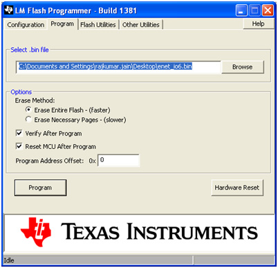
Programà browse .bin file from computer locationà program. Here we will see that a debug out of LED (red) will glow on TI’s evaluation board.

Fig. 2: Screenshot of LM Flash Programmer’s Application on Windows Operating System
Caution: It there are any changes in project source file then rebuild the project for updated .bin file.
Note: MAC address should also be programmed using LM flash programmer.
Filed Under: Electronic Projects


Questions related to this article?
👉Ask and discuss on Electro-Tech-Online.com and EDAboard.com forums.
Tell Us What You Think!!
You must be logged in to post a comment.