Multi-tasking Operating Systems can run several processes at a time creating and effect of parallel processing with the help of the high speed processor. The Linux Operating Systems provides Multi-User-Multitasking. Linux operating systems especially Ubuntu is preferred for all kind of programming and development. In a multi-tasking environment of the Operating System several processes executes at the same time and the Signals provide an Inter-Process Communication (IPC) method. The Operating System sends signals to the process to notify them about the events occurred along with passing a value or message.
The Raspberrypi is a mini-computer board which is powerful enough to run large operating systems like Linux, Mac and Windows. The Linux operating systems like Archlinux ARM, OpenELEC, Pidora, Raspbmc, RISC OS and the Raspbian and also Ubuntu versions are available for the Raspberrypi board. The device which uses the Broadcom controller chip which is a SoC (System on Chip). This SoC has the ARM11 processor which runs on 700 MHz at its core. This powerful processor and the controller having the peripherals like timers, interrupt controller, GPIO,, PCM / I2S, DMA controller, I2C, SPI slave, PWM, UART, USB, graphical processing unit (GPU) which includes VideoCore, MPEG-2 and MPEG-4 and a 512 MB SDRAM makes it a mini-computer.
Those who have worked on simple microcontrollers know how difficult it is to continuously check for an input pin status without affecting the other task of the microcontroller like displaying and SSD, playing a music etc. In a Multitasking environment of an Operating system like Ubuntu a separate process can be created for checking the status of input pin and then notify the main process whenever their status changes. The process that has been created for different input pins may generate the same signal but with different values along with them. The main process can identify input pin corresponding to the signal received based on the value read from the signal information.
[[wysiwyg_imageupload:10615:]]
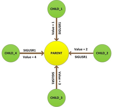
In this particular project a Parent creates 4 Childs processes which are then used to read the status of the four input pins independently. The Child processes are made to send a signal ‘SIGUSR1’ to the Parent process whenever the status of the input pin changes. Each Child process sends a different value along with the signals they sent. As soon as the Parent process receives a signal, it reads the value from the signal and changes the status of the corresponding output pin. This forms a Process System made up of 4 Child process and a Parent process where the Parent is free to do its work, but the Child can get the attention of the Parent by sending signal. The diagrammatic representation of the Process System is given below:
In this project the Raspberrypi board is loaded with Ubuntu and is remotely accessed using VNC. The Raspberrypi board is also connected to the internet. There are 26 connectors which can be taken out from the connector port of the Raspberrypi board. All the connector pins are taken out using 13*2 pin female connectors and at the other end of their wire 26 pin Burg stick male connectors are attached. The Burg stick male connectors allow each pin out from the Raspberrypi board to be plugged into the holes of a breadboard. To access the pins that coming out of the Broadcom controller the C library “bcm2835” has been downloaded and installed.
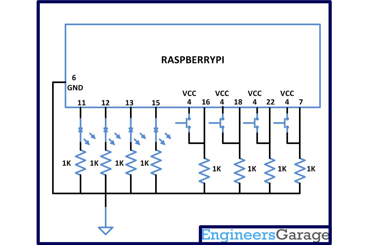
There are eight general purpose IO pins on the 13*2 pin connectors of the Raspberrypi board and among them four pins has been selected as input and then remaining four pins as output. The input pins are connected to push button and are pulled down using 1K resistors. The output pins are connected to the LEDs through another set of 1K resistors.
Four separate input reading processes has been created as Child process using the fork () function for each of the input pins. This Child processes continuously reads the particular input pin and sends a signal to the Parent process using kill () function whenever the status of the pin changes.
For separate input reading and output writing the functions from the library <bcm2835.h> is used. The function ‘bcm2835_gpio_fsel ()’ is used to set the pins as input or output and the function ‘bcm2835_gpio_set_pud ()’ is used to turn off the pull up/down from the pin. The function ‘bcm2835_gpio_lev ()’ is used to read the value of the pin and ‘bcm2835_gpio_write ()’ is used to write the value to the output pin.
A function called ‘sigqueue ()’ is available in the <signal.h> which can be used to send values or messages along with the signals. In this project a function is written based on the ‘sigqueue ()’ to send value along with signals to another process. The function is called ‘sig_send_val ()’ and can be used to send a particular signal to a particular process along with a value. The function has three arguments, one for the process id, one for the signal number and the other for the value to be sent. The prototype of the function is given below;
void sig_send_val ( pid_t id, int signo, int val );
The following is the code for a Child process which will send a signal ‘SIGUSR1’ to the Parent along with a value 1, whenever the state of an input pin defined as IN_PIN1 changes with the help of ‘sig_send_val ()’
void signal_on_state_change_pin1 ( void )
{
while ( 1 ) // for continuous read
{
if ( bcm2835_gpio_lev ( IN_PIN1 ) ) // checking if pin is high
{
delay ( 50 );
if ( bcm2835_gpio_lev ( IN_PIN1 ) ) // confirming pin high after a delay
{
// send SIGUSR1 signal to parent along with a value 1
sig_send_val ( getppid (), SIGUSR1, 1 );
do // loop until pin becomes low again
{
while ( bcm2835_gpio_lev ( IN_PIN1 ) ) // wait till pin low
delay ( 1 );
delay ( 50 ); // confirm low after this delay
}
while ( bcm2835_gpio_lev ( IN_PIN1 ) );
// send SIGUSR1 signal to parent along with a value 1
sig_send_val ( getppid (), SIGUSR1, 1 );
}
else;
}else;
delay ( 1 );
}
}
In this project the function written to set the required function as Signal Handler using the ‘sigaction ()’ function is ‘sig_set_handler ()’. This function can be used to set a particular function as the Signal Handler for a particular signal number and hence the function has only two arguments, one for the signal number and the other for the function that need to be set as the Signal Handler. The prototype of the function is given below;
void sig_set_handler ( int signo, void *handler );
For example to set the following function as the Signal Handler using the ‘sig_set_handler ()’ for a signal ‘SIGUSR1’
void button_signal_handler ( int sig, siginfo_t *siginfo, void *context );
use the following statement in the main function;
sig_set_handler ( SIGUSR1, &button_signal_handler );
The following is the code for a Parent process’s Signal Handler reading the values from the signal received and comparing the values with a preset value to perform the action of changing state of a corresponding output pin, where an LED is connected.
void button_signal_handler ( int sig, siginfo_t *siginfo, void *context )
{
static char led1 = 0; static char led2 = 0;
static char led3 = 0; static char led4 = 0;
if ( 1 == *( ( int * ) &siginfo -> si_value ) )
{
led1 = ~led1;
bcm2835_gpio_write ( OUT_PIN1, led1 );
}else;
if ( 2 == *( ( int * ) &siginfo -> si_value ) )
{
led2 = ~led2;
bcm2835_gpio_write ( OUT_PIN2, led2 );
}else;
if ( 3 == *( ( int * ) &siginfo -> si_value ) )
{
led3 = ~led3;
bcm2835_gpio_write ( OUT_PIN3, led3 );
}else;
if ( 4 == *( ( int * ) &siginfo -> si_value ) )
{
led4 = ~led4;
bcm2835_gpio_write ( OUT_PIN4, led4 );
}else;
}
The structure pointer ‘siginfo -> si_value’ is of a different type other than the integer and hence to use that inside an if-condition the following type casting to integer type has been done;
*( ( int * ) &siginfo -> si_value )
Project Source Code
###
#include <bcm2835.h> #include <pthread.h> #include <unistd.h> #include <signal.h> #include <sys/time.h> #include <stdlib.h>#define IN_PIN1 RPI_GPIO_P1_07
#define IN_PIN2 RPI_GPIO_P1_22
#define IN_PIN3 RPI_GPIO_P1_18
#define IN_PIN4 RPI_GPIO_P1_16#define OUT_PIN1 RPI_GPIO_P1_15
#define OUT_PIN2 RPI_V2_GPIO_P1_13
#define OUT_PIN3 RPI_GPIO_P1_12
#define OUT_PIN4 RPI_GPIO_P1_11void set_pins_input ( void );
void set_pins_output ( void );
void set_output_pins_low ( void );
void button_signal_handler ( int sig, siginfo_t *siginfo, void *context );
void signal_on_state_change_pin1 ( void );
void signal_on_state_change_pin2 ( void );
void signal_on_state_change_pin3 ( void );
void signal_on_state_change_pin4 ( void );
void sig_set_handler ( int signo, void *handler );
void sig_send_val ( pid_t id, int signo, int val );
pid_t child_id [ 5 ];int main ( void )
{
int i;if (!bcm2835_init())
return 1;
set_pins_output ();
set_output_pins_low ();
set_pins_input ();
delay ( 100 );
sig_set_handler ( SIGUSR1, &button_signal_handler );if ( ! ( child_id [ 0 ] = fork () ) )
{
signal_on_state_change_pin1 ();
_exit ( 0 );
}
else;if ( ! ( child_id [ 1 ] = fork () ) )
{
signal_on_state_change_pin2 ();
_exit ( 0 );
}
else;if ( ! ( child_id [ 2 ] = fork () ) )
{
signal_on_state_change_pin3 ();
_exit ( 0 );
}
else;if ( ! ( child_id [ 3 ] = fork () ) )
{
signal_on_state_change_pin4 ();
_exit ( 0 );
}
else;while ( 1 )
delay ( 1 );bcm2835_close();
return 0;
}void signal_on_state_change_pin1 ( void )
{
while ( 1 )
{
if ( bcm2835_gpio_lev ( IN_PIN1 ) )
{
delay ( 50 );
if ( bcm2835_gpio_lev ( IN_PIN1 ) )
{
sig_send_val ( getppid (), SIGUSR1, 1 );
do
{
while ( bcm2835_gpio_lev ( IN_PIN1 ) )
delay ( 1 );
delay ( 50 );
}
while ( bcm2835_gpio_lev ( IN_PIN1 ) );sig_send_val ( getppid (), SIGUSR1, 1 );
}
else;
}else;
delay ( 1 );
}
}void signal_on_state_change_pin2 ( void )
{
while ( 1 )
{
if ( bcm2835_gpio_lev ( IN_PIN2 ) )
{
delay ( 50 );
if ( bcm2835_gpio_lev ( IN_PIN2 ) )
{
sig_send_val ( getppid (), SIGUSR1, 2 );
do
{
while ( bcm2835_gpio_lev ( IN_PIN2 ) )
delay ( 1 );
delay ( 50 );
}
while ( bcm2835_gpio_lev ( IN_PIN2 ) );
sig_send_val ( getppid (), SIGUSR1, 2 );
}
else;
}else;
delay ( 1 );
}
}void signal_on_state_change_pin3 ( void )
{
while ( 1 )
{
if ( bcm2835_gpio_lev ( IN_PIN3 ) )
{
delay ( 50 );
if ( bcm2835_gpio_lev ( IN_PIN3 ) )
{
sig_send_val ( getppid (), SIGUSR1, 3 );
do
{
while ( bcm2835_gpio_lev ( IN_PIN3 ) )
delay ( 1 );
delay ( 50 );
}
while ( bcm2835_gpio_lev ( IN_PIN3 ) );sig_send_val ( getppid (), SIGUSR1, 3 );
}
else;
}else;
delay ( 1 );
}
}void signal_on_state_change_pin4 ( void )
{
while ( 1 )
{
if ( bcm2835_gpio_lev ( IN_PIN4 ) )
{
delay ( 50 );
if ( bcm2835_gpio_lev ( IN_PIN4 ) )
{
sig_send_val ( getppid (), SIGUSR1, 4 );
do
{
while ( bcm2835_gpio_lev ( IN_PIN4 ) )
delay ( 1 );
delay ( 50 );
}
while ( bcm2835_gpio_lev ( IN_PIN4 ) );sig_send_val ( getppid (), SIGUSR1, 4 );
}
else;
}else;
delay ( 1 );
}
}void button_signal_handler ( int sig, siginfo_t *siginfo, void *context )
{
static char led1 = 0; static char led2 = 0;
static char led3 = 0; static char led4 = 0;
if ( 1 == *( ( int * ) &siginfo -> si_value ) )
{
led1 = ~led1;
bcm2835_gpio_write ( OUT_PIN1, led1 );
}else;if ( 2 == *( ( int * ) &siginfo -> si_value ) )
{
led2 = ~led2;
bcm2835_gpio_write ( OUT_PIN2, led2 );
}else;if ( 3 == *( ( int * ) &siginfo -> si_value ) )
{
led3 = ~led3;
bcm2835_gpio_write ( OUT_PIN3, led3 );
}else;if ( 4 == *( ( int * ) &siginfo -> si_value ) )
{
led4 = ~led4;
bcm2835_gpio_write ( OUT_PIN4, led4 );
}else;}
void set_output_pins_low ( void )
{
bcm2835_gpio_write ( OUT_PIN1, LOW);
bcm2835_gpio_write ( OUT_PIN2, LOW);
bcm2835_gpio_write ( OUT_PIN3, LOW);
bcm2835_gpio_write ( OUT_PIN4, LOW);
}void set_pins_output ( void )
{
bcm2835_gpio_fsel ( OUT_PIN1, BCM2835_GPIO_FSEL_OUTP );
bcm2835_gpio_fsel ( OUT_PIN2, BCM2835_GPIO_FSEL_OUTP );
bcm2835_gpio_fsel ( OUT_PIN3, BCM2835_GPIO_FSEL_OUTP );
bcm2835_gpio_fsel ( OUT_PIN4, BCM2835_GPIO_FSEL_OUTP );
}void set_pins_input ( void )
{
bcm2835_gpio_fsel ( IN_PIN1, BCM2835_GPIO_FSEL_INPT );
bcm2835_gpio_set_pud ( IN_PIN1, BCM2835_GPIO_PUD_OFF );bcm2835_gpio_fsel ( IN_PIN2, BCM2835_GPIO_FSEL_INPT );
bcm2835_gpio_set_pud ( IN_PIN2, BCM2835_GPIO_PUD_OFF );bcm2835_gpio_fsel ( IN_PIN3, BCM2835_GPIO_FSEL_INPT );
bcm2835_gpio_fsel ( IN_PIN3, BCM2835_GPIO_FSEL_INPT );bcm2835_gpio_set_pud ( IN_PIN4, BCM2835_GPIO_PUD_OFF );
bcm2835_gpio_set_pud ( IN_PIN4, BCM2835_GPIO_PUD_OFF );
}void sig_send_msg ( pid_t id, int signo, char *msg )
{
union sigval *sigdata;
sigdata = malloc ( sizeof ( union sigval ) );
sigdata -> sival_ptr = msg;sigqueue ( id, signo, *sigdata );
free ( sigdata );
}void sig_send_val ( pid_t id, int signo, int val )
{
union sigval *sigdata;
sigdata = malloc ( sizeof ( union sigval ) );
sigdata -> sival_int = val;sigqueue ( id, signo, *sigdata );
free ( sigdata );
}void sig_set_handler ( int signo, void *handler )
{
struct sigaction *act;
act = malloc ( sizeof ( struct sigaction ) );
act -> sa_sigaction = handler;
act -> sa_flags = SA_SIGINFO;sigaction ( signo, act, NULL );
}
###
Circuit Diagrams
Project Components
Project Video
Filed Under: Raspberry pi
Filed Under: Raspberry pi

Questions related to this article?
👉Ask and discuss on EDAboard.com and Electro-Tech-Online.com forums.
Tell Us What You Think!!
You must be logged in to post a comment.