Engineers Garage

  • Electronic Projects & Tutorials
    • Electronic Projects
      • Arduino Projects
      • AVR
      • Raspberry pi
      • ESP8266
      • BeagleBone
      • 8051 Microcontroller
      • ARM
      • PIC Microcontroller
      • STM32
    • Tutorials
      • Audio Electronics
      • Battery Management
      • Brainwave
      • Electric Vehicles
      • EMI/EMC/RFI
      • Hardware Filters
      • IoT tutorials
      • Power Tutorials
      • Python
      • Sensors
      • USB
      • VHDL
    • Circuit Design
    • Project Videos
    • Components
  • Articles
    • Tech Articles
    • Insight
    • Invention Stories
    • How to
    • What Is
  • News
    • Electronic Product News
    • Business News
    • Company/Start-up News
    • DIY Reviews
    • Guest Post
  • Forums
    • EDABoard.com
    • Electro-Tech-Online
    • EG Forum Archive
  • DigiKey Store
    • Cables, Wires
    • Connectors, Interconnect
    • Discrete
    • Electromechanical
    • Embedded Computers
    • Enclosures, Hardware, Office
    • Integrated Circuits (ICs)
    • Isolators
    • LED/Optoelectronics
    • Passive
    • Power, Circuit Protection
    • Programmers
    • RF, Wireless
    • Semiconductors
    • Sensors, Transducers
    • Test Products
    • Tools
  • Learn
    • eBooks/Tech Tips
    • Design Guides
    • Learning Center
    • Tech Toolboxes
    • Webinars & Digital Events
  • Resources
    • Digital Issues
    • EE Training Days
    • LEAP Awards
    • Podcasts
    • Webinars / Digital Events
    • White Papers
    • Engineering Diversity & Inclusion
    • DesignFast
  • Guest Post Guidelines
  • Advertise
  • Subscribe

How to Reset EEPROM (24C02) Memory using 8051 microcontroller- (Part 42/45)

By Himanshu Choudhary November 13, 2010

AT24C02 is two-wire serially programmable EEPROM. This means that for programming, the data and control signals are provided serially along with clock signals from the other wire. The read-write operations are accomplished by sending a set of control signals including the address and/or data bits from a microcontroller.

This project demonstrates the memory reset operation of a 24C02 IC by using AT89C51. For basic operations of AT24C02, refer interfacing serial EEPROM with 8051. It writes & reads a byte to/from the EEPROM displaying it on a 16x2 LCD, and then resets the memory. The results can be monitored on the LCD display.


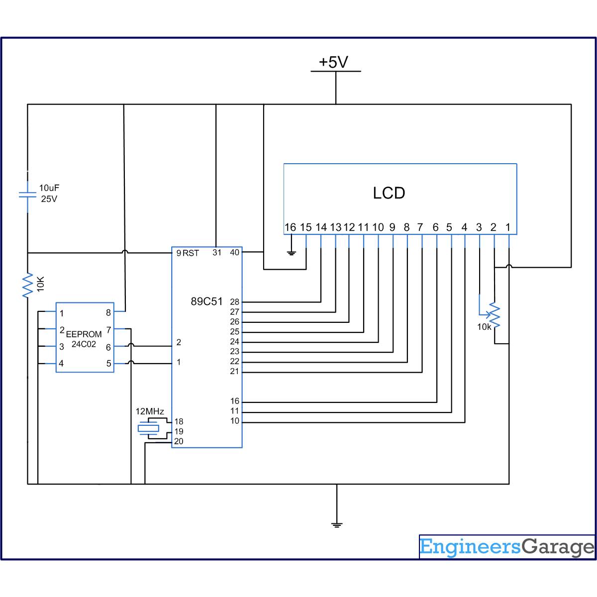
AT24C02 is a two-wire serial EEPROM from Atmel. 24C02 is an 8 pin IC and reads 8 bit data serially. Its memory size is 2KB. Pins 1- 3 are address pins which are connected to ground. Pin 4 is GND; Pin 5 is SDA (serial data); and pin 6 is SCL (serial clock input). Pin 7 is WP (write protect) pin and is connected to GND. Pin 8 is Vcc for providing power supply. For details on its interfacing and operation, refer interfacing 24C02 with 8051.

The microcontroller monitors the start, stop, acknowledge, send, save, read instructions of EEPROM. The memory can be reset after a power loss, a system reset or an interruption in protocol. The project resets memory after a write and read operation continuously.
 
To reset memory, EEPROM is clocked nine times followed by the start condition. For this, a high SDA signal is looked for in each cycle while SCL is high, i.e., acknowledge function is called 9 times.
 
Memory Reset Clock Cycle Condition
Fig. 2: Memory Reset Clock Cycle condition
 
SDA and SCL pins are connected to P1.0 and P1.1 of AT89C51 and through these pins, serial data transfer takes place. Port P2 of microcontroller is used for connecting LCD data pin while control pins of LCD (RS, RW & EN) are connected to P3.0, P3.1 and P3.6 of the controller. For more details, refer LCD interfacing with AT89C51.  


Start condition:
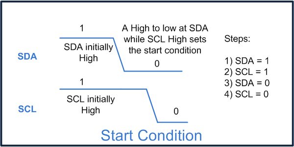
Any read or write operation in EEPROM is initiated by Start condition. This occurs when there is a high to low transition of SDA while SCL is high. (Refer the following diagram) This tells the EEPROM that words from the controller are ready for it. SCL is set low at the end of start condition. This is because any read or write operation first involves transfer of some words to EEPROM. That requires a low to high transition of clock corresponding to each bit of the word.
 
Start Condition To Initialize EEPROM
Fig. 3: Start Condition to initialize EEPROM

Clocking:
When a sequence of words is transferred to EEPROM, a clock is needed to be sent by the controller after transmission of each word. This is required so that the controller can receive its acknowledgement. Clock is just a high transition followed by a low transition of SCL when the initial clock signal is low.
 
Clocking Condition For Acknowledgemnt In EEPROM
Fig. 4: Clocking Condition for acknowledgemnt in EEPROM


Project Source Code

###

//Program for Memory Reset of Serial EEPROM 24C02 using 8051 microcontroller (AT89C51) #include<reg51.h>
#include<intrins.h>		//For using [_nop_()] 'No operation'
sbit sda=P1^0;
sbit scl=P1^1;
sbit led=P0^3;
bit ack;
sbit led1=P0^1;
sfr lcd_data_pin=0xA0;		//Port P2
sfr output=0x80;			//Port P0
sbit rs=P3^0;
sbit rw=P3^1;
sbit en=P3^6;
unsigned char reead,write,write2,i,j;
unsigned int temp;
void delay(unsigned int count)
{
	int i,j;
	for(i=0;i<count;i++)
		for(j=0;j<1275;j++);
}
void lcd_command(unsigned char comm)
{
	lcd_data_pin=comm;
	en=1;
	rs=0;
	rw=0;
	delay(1);
	en=0;
}
void lcd_data(unsigned char disp)
{
	lcd_data_pin=disp;
	en=1;
	rs=1;
	rw=0;
	delay(1);
	en=0;
}
lcd_dataa(unsigned char *disp)
{
	int x;
	for(x=0;disp[x]!=0;x++)
	{
		lcd_data(disp[x]);
	}
}
void lcd_ini()
{
	lcd_command(0x38);		  // for using 8-bit 2 row LCD 
	delay(5);
	lcd_command(0x0F);        // for display on cursor blinking
	delay(5);
	lcd_command(0x80);
	delay(5);
}
void aknowledge()
{
	scl=1;
	_nop_();
	_nop_();
	scl=0;
} 
void start()		//Start condition
{
	sda=1;
	scl=1;
	_nop_();
	_nop_();
	sda=0;
	scl=0;
}
void stop()			//Stop condition
{
	sda=0;
	scl=1;
	_nop_();
	_nop_(); 
    sda=1;
	scl=0;
}
void send_byte(unsigned char value)
{
	unsigned int i;
	unsigned char send;
	send=value;
	for(i=0;i<8;i++)
	{
		sda=send/128;
		send=send<<1;
		scl=1;
		_nop_();
		_nop_();
		scl=0;
	}
	ack=sda;
	sda=0;
}
unsigned char read_byte()
{
	unsigned int i;
	sda=1;
	reead=0;
	for(i=0;i<8;i++)
	{
		reead=reead<<1;
		scl=1;
		_nop_();
		_nop_();
		if(sda==1)
			reead++;
		scl=0;
	}
	sda=0;
	return reead;
}		
void Read()			//Read operation
{
	start();
	send_byte(0xA0);
	aknowledge();
	send_byte(0x00);
	aknowledge();
	start();
	send_byte(0xA1);
	aknowledge();
	i=read_byte();
	aknowledge();
	j=read_byte();
	aknowledge();
	stop();
	if(i==5)
	{
		led=0;
		delay(100);
		led=1;
		delay(100);
		write=i+48;
		lcd_command(0xC6);
		lcd_data(write);	
	}
	else
	{
		led=1;
		lcd_command(0xC6);
		lcd_dataa(' ');
	}
	if(j==65)
	{
		lcd_command(0xC7);
		lcd_data(j);
	}
	else
	{
	    lcd_command(0xC7);
		lcd_data(' ');
	}
	aknowledge();
	i=0;
	j=0;
}

void main()
{
	int k,l,m=0;
	k=0;
	l=0;
	lcd_ini();
	lcd_dataa("Sent :");
	lcd_command(0xC0);
	lcd_dataa("Read :");
	temp=0;
	start();
	while(1)
	{
		while(k<9)        //9 times cycle
		{ 
			k++;
			aknowledge();
		}
		if(k==9)
		{
			k=0;
			start();        //Start condition after 9 times clocking
		}
		Read();
	}
}

###


Circuit Diagrams

Circuit-Diagram-EEPROM-24C02-Memory-Reset-Using-8051-Microcontroller-AT89C51

Project Components

  • AT89C51 Microcontroller
  • LCD
  • Serial EEPROM AT24C02

Project Video

Download:
FLVMP43GP


Filed Under: 8051 Microcontroller
Tagged With: 8051, eeprom, microcontroller
 

Next Article

← Previous Article
Next Article →

Questions related to this article?
👉Ask and discuss on EDAboard.com and Electro-Tech-Online.com forums.


Tell Us What You Think!! Cancel reply

You must be logged in to post a comment.

EE TECH TOOLBOX

“ee
Tech Toolbox: 5G Technology
This Tech Toolbox covers the basics of 5G technology plus a story about how engineers designed and built a prototype DSL router mostly from old cellphone parts. Download this first 5G/wired/wireless communications Tech Toolbox to learn more!

EE Learning Center

EE Learning Center
“engineers
EXPAND YOUR KNOWLEDGE AND STAY CONNECTED
Get the latest info on technologies, tools and strategies for EE professionals.

HAVE A QUESTION?

Have a technical question about an article or other engineering questions? Check out our engineering forums EDABoard.com and Electro-Tech-Online.com where you can get those questions asked and answered by your peers!


RSS EDABOARD.com Discussions

  • How to improve the reliability of RS485 communication?
  • The Analog Gods Hate Me
  • Battery Deep Discharge – IC Workarounds?
  • Safe Current and Power Density Limits in PCB Copper(in A/m² and W/mÂł) simulation
  • Why so few Phase shift full bridge controllers?

RSS Electro-Tech-Online.com Discussions

  • Simple LED Analog Clock Idea
  • The Analog Gods Hate Me
  • Wideband matching an electrically short bowtie antenna; 50 ohm, 434 MHz
  • PIC KIT 3 not able to program dsPIC
  • Parts required for a personal project

Featured – LoRa/LoRaWan Series

  • What is the LoRaWAN network and how does it work?
  • Understanding LoRa architecture: nodes, gateways, and servers
  • Revolutionizing RF: LoRa applications and advantages
  • How to build a LoRa gateway using Raspberry Pi
  • How LoRa enables long-range communication
  • How communication works between two LoRa end-node devices

Recent Articles

  • Tria modules integrate edge AI processing with multi-core processors
  • pSemi introduces RF switch with 52 dBm PMAX,PEAK and 90-dBm IIP3 linearity
  • XP Power launches 1.3 kW power supply with 58.9 W/cmÂł density
  • How to enable Wi-Fi provisioning in ESP32-based IoT products
  • Amphenol RF introduces FAKRA to SMA adapters with 4 GHz operating frequency

EE ENGINEERING TRAINING DAYS

engineering

Submit a Guest Post

submit a guest post
Engineers Garage
  • Analog IC TIps
  • Connector Tips
  • Battery Power Tips
  • DesignFast
  • EDABoard Forums
  • EE World Online
  • Electro-Tech-Online Forums
  • EV Engineering
  • Microcontroller Tips
  • Power Electronic Tips
  • Sensor Tips
  • Test and Measurement Tips
  • 5G Technology World
  • Subscribe to our newsletter
  • About Us
  • Contact Us
  • Advertise

Copyright © 2025 WTWH Media LLC. All Rights Reserved. The material on this site may not be reproduced, distributed, transmitted, cached or otherwise used, except with the prior written permission of WTWH Media
Privacy Policy

Search Engineers Garage

  • Electronic Projects & Tutorials
    • Electronic Projects
      • Arduino Projects
      • AVR
      • Raspberry pi
      • ESP8266
      • BeagleBone
      • 8051 Microcontroller
      • ARM
      • PIC Microcontroller
      • STM32
    • Tutorials
      • Audio Electronics
      • Battery Management
      • Brainwave
      • Electric Vehicles
      • EMI/EMC/RFI
      • Hardware Filters
      • IoT tutorials
      • Power Tutorials
      • Python
      • Sensors
      • USB
      • VHDL
    • Circuit Design
    • Project Videos
    • Components
  • Articles
    • Tech Articles
    • Insight
    • Invention Stories
    • How to
    • What Is
  • News
    • Electronic Product News
    • Business News
    • Company/Start-up News
    • DIY Reviews
    • Guest Post
  • Forums
    • EDABoard.com
    • Electro-Tech-Online
    • EG Forum Archive
  • DigiKey Store
    • Cables, Wires
    • Connectors, Interconnect
    • Discrete
    • Electromechanical
    • Embedded Computers
    • Enclosures, Hardware, Office
    • Integrated Circuits (ICs)
    • Isolators
    • LED/Optoelectronics
    • Passive
    • Power, Circuit Protection
    • Programmers
    • RF, Wireless
    • Semiconductors
    • Sensors, Transducers
    • Test Products
    • Tools
  • Learn
    • eBooks/Tech Tips
    • Design Guides
    • Learning Center
    • Tech Toolboxes
    • Webinars & Digital Events
  • Resources
    • Digital Issues
    • EE Training Days
    • LEAP Awards
    • Podcasts
    • Webinars / Digital Events
    • White Papers
    • Engineering Diversity & Inclusion
    • DesignFast
  • Guest Post Guidelines
  • Advertise
  • Subscribe