The EEPROM stands for Electrically Erasable Programmable Read Only Memory. In an EEPROM the data can be written with the help of electrically programming the chip. EEPROM memory is widely used in microcontroller systems where some particular data need to be retained each time the system is turned on and to save particular data before the system is powered off.
The Arduino board has an AVR microcontroller in it which also has a built-in EEPROM memory. The memory size varies with the Arduino boards and the microcontroller used in them.
The microcontroller can read the analog input voltage by sampling it and converting it to their digital values with the help of Analog to Digital Converter (ADC). The microcontroller can also generate an analog voltage on any external device with the help of Pulse Width Modulated (PWM) waves. Most of the microcontrollers have built-in PWM module and ADC modules which helps them in reading analog voltage inputs and generating analog voltage outputs on an external device.
In this project the Arduino pro-mini board is programmed with the help of Arduino IDE version 1.0.3 on windows operating system. The image of the Arduino pro-mini board and the Arduino IDE is shown in the following;

Fig. 2: Typical Arduino Pro-Mini Board

Fig. 3: Arduino IDE Software Window
Another hardware which can perform the USB to TTL conversion is used to upload the program into the arduino board.

Fig. 4: External USB to TTL converter board for programming Arduino and serial communication
It is assumed that the reader has gone through the project how to get started with the arduino and done all the things discussed in it. In this particular project a simple potentiometer is used to provide variable voltage to the analog pin as a sensor does and which can be replaced with an actual sensor in future projects. The variable pin of a potentiometer is connected to the analog pin; in this project the pin A0. The other two pins of the potentiometer is connected to the VCC and GND so that as the variable moves it can divide the entire supply voltage and provide it as the analog input voltage for the Arduino board.
Once a value is read from the sensor it is immediately mapped and written to a pin configured as the analog output and where an LED is connected in the circuit. The brightness of the LED indicates the voltage output from the sensor. The value read is also converted to its voltage equivalent and displayed in an LCD and at the same time stored in an EEPROM. The functions analogRead(),analogWrite() and map() which can be used to read, write and map the values respectively and also the method to convert the value to the actual voltage are already explained in previous projects on how to use analog input and output of an Arduino board, how to display the sensor values using Arduino, and how to make dynamic sensor display using arduino.
The last read value, the present value and the other data are displayed on a 16*2 LCD using the functions provided by the library <LiquidCrystal.h>. Few functions from the library <LiquidCrystal.h> including those which are used in this particular project are already discussed in the previous projects onhow to interface an LCD, how to display sensor value on LCD, how to connect the LCD with the PC and how to make an LCD scrolling display.
The Arduino pro-mini has ATMEGA328 microcontroller which has 1Kb of EEPROM memory. The EEPROM memory is accessed in the code with the help of functions provided by the library <EEPROM.h>. The projects on how to access the EEPROM of the Arduino and how to perform the EEPROM test of the Arduino explains the method of reading and writing the EEPROM memory of the Arduino.
There are basically two functions namely EEPROM.write() and EEPROM.read() which helps in writing data to the EEPROM memory and reading data from the EEPROM memory respectively. The details of the functions are explained in the following section.
EEPROM.write()
The function EEPROM.write() is used to write a data byte into a particular address of the EEPROM memory mentioned by the parameters passed to the function. The function has two parameters where the first one should be provided with the address of the EEPROM location into which the data need to be written into and the second parameter should be provided with actual data byte. For example if the data ‘A’ need to be written into the address mentioned by the variable ‘addr’ the following statement can be used.
EEPROM.write(addr, ‘A’);
EEPROM.read()
The function EEPROM.read() is used to read a particular data byte from the internal EEPROM of the Arduino’s microcontroller. The function has a single parameter which is the address from which the data should be read from. The function has a return value which is the actual data byte which it read from the address mentioned by the parameter passed into it. For example if the data byte is to be read from the location mentioned by the variable ‘addr’ the following statement can be used.
EEPROM.read(addr);
THE CODE
The Arduino board reads the analog value at the analog input channel using the function analogRead() and then maps the value to the range 0 to 255 so that it can be written into the PWM module. The function map() is used to map the value from the range 0 to 1023 to the range 0 to 255. The mapped value is immediately written to the pin which is selected as the analog output pin using the function analogWrite() and hence varying the brightness of an LED indicator connected to that pin.
The mapped value is then converted to the actual voltage value which is then stored in the internal EEPROM with the help of functions from the library <EEPROM.h>. The function EEPROM.write() is used for writing the value into a particular memory location. The value is also displayed in a 16*2 LCD.
Whenever the Arduino is powered up the code first reads the previously stored value from the same memory location and displays it on a 16*2 LCD. The function from the library <EEPROM.h> namely EEPROM.read() is used to read the value from the memory location.
Both the previous value read from the location is and the current value reads from the analog pin are displayed in a 16*2 LCD with the help of functions from the library <LiquidCrystal.h>. Few functions from the library <LiquidCrystal.h> including those which are used in this particular project are already discussed in the previous projects on how to interface an LCD, how to display sensor value on LCD, how to connect the LCD with the PC and how to make an LCD scrolling display.
When the coding is finished one can verify and upload the code to the Arduino board as explained in the project how to get started with the Arduino. First time when the Arduino is powere up the last value displayed will be 0 and from the next time onwards it will display the last value sensed before the Arduino is powered off.
Project Source Code
###


/*================================= EG LABS =======================================

Read a sensor value and store it in EEPROM before power off

 The circuit:

 * LED attached from pin 6 to ground through a 1K resistor

 * Potentiometer attached to analog input A0

 * one side pin (either one) to ground

 * the other side pin to +5V

 LCD:

 * LCD RS pin to digital pin 12

 * LCD Enable pin to digital pin 11

 * LCD D4 pin to digital pin 5

 * LCD D5 pin to digital pin 4

 * LCD D6 pin to digital pin 3

 * LCD D7 pin to digital pin 2

 * LCD R/W pin to ground

 * 10K resistor:

 * ends to +5V and ground

 * wiper to LCD pin 3

 * LED anode attached to digital output 6

 * LED cathode attached to ground through a 1K resistor

//================================= EG LABS =======================================*/


#include <EEPROM.h>

#include <LiquidCrystal.h>


LiquidCrystal lcd(12, 11, 5, 4, 3, 2);               // initialize the LCD library with the numbers of the interface pins


const int analogInPin = A0;                          // Analog input pin that the potentiometer is attached to

const int analogOutPin = 6;                          // Analog output pin that the LED is attached to

int potvalue = 0;

int outputvalue = 0;


int address = 50;                                    // the variable which holds the address in the eeprom

int read_value = 0;                                  // the variable which holds the data which is read from the eeprom


int led = 6;                                         // variable which holds the pin number at which the LED is connected


void setup()

{

  pinMode(led, OUTPUT);                               // initialize the led pin as an output.


  lcd.begin(16, 2);                                   // set up the LCD's number of columns and rows:

  lcd.print("ENGINEERS GARAGE");

  delay(2000);

  lcd.clear();

  lcd.print("LAST VALUE : ");

  read_value = EEPROM.read(address);                  // read the value from the address

  lcd.print(read_value);

  lcd.print('v');

  delay(2000);

  lcd.clear();

}

void loop()

{

  potvalue = analogRead(analogInPin);

  outputvalue = map(potvalue, 0, 1023, 0, 255);

  analogWrite(analogOutPin, outputvalue);

  lcd.setCursor(0, 0);

  lcd.print("  SENSOR VALUE");

  lcd.setCursor(7, 2);

  lcd.print((outputvalue * 5)/255);

  lcd.print("V");

  EEPROM.write(address, ((outputvalue * 5)/255));                 // write the value to the EEPROM address

}

###
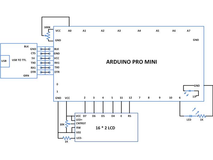
Circuit Diagrams
Project Components
Project Video
Filed Under: Arduino
Filed Under: Arduino

Questions related to this article?
👉Ask and discuss on Electro-Tech-Online.com and EDAboard.com forums.
Tell Us What You Think!!
You must be logged in to post a comment.