Engineers Garage

  • Electronic Projects & Tutorials
    • Electronic Projects
      • Arduino Projects
      • AVR
      • Raspberry pi
      • ESP8266
      • BeagleBone
      • 8051 Microcontroller
      • ARM
      • PIC Microcontroller
      • STM32
    • Tutorials
      • Audio Electronics
      • Battery Management
      • Brainwave
      • Electric Vehicles
      • EMI/EMC/RFI
      • Hardware Filters
      • IoT tutorials
      • Power Tutorials
      • Python
      • Sensors
      • USB
      • VHDL
    • Circuit Design
    • Project Videos
    • Components
  • Articles
    • Tech Articles
    • Insight
    • Invention Stories
    • How to
    • What Is
  • News
    • Electronic Product News
    • Business News
    • Company/Start-up News
    • DIY Reviews
    • Guest Post
  • Forums
    • EDABoard.com
    • Electro-Tech-Online
    • EG Forum Archive
  • DigiKey Store
    • Cables, Wires
    • Connectors, Interconnect
    • Discrete
    • Electromechanical
    • Embedded Computers
    • Enclosures, Hardware, Office
    • Integrated Circuits (ICs)
    • Isolators
    • LED/Optoelectronics
    • Passive
    • Power, Circuit Protection
    • Programmers
    • RF, Wireless
    • Semiconductors
    • Sensors, Transducers
    • Test Products
    • Tools
  • Learn
    • eBooks/Tech Tips
    • Design Guides
    • Learning Center
    • Tech Toolboxes
    • Webinars & Digital Events
  • Resources
    • Digital Issues
    • EE Training Days
    • LEAP Awards
    • Podcasts
    • Webinars / Digital Events
    • White Papers
    • Engineering Diversity & Inclusion
    • DesignFast
  • Guest Post Guidelines
  • Advertise
  • Subscribe

How To Test The SPI Module Of Arduino- (Part 32/49)

By Ajish Alfred July 18, 2013

Any AVR microcontroller based board which follows the standard arduino schematic and is flashed with the arduino boot-loader can be called an arduino board. All arduino boards should be compatible with the arduino IDE which can be used to program the arduino boards. The arduino IDE is also open source and anybody can contribute their libraries to the arduino.  The arduino is refered to as open source hardware, since the standard schematic is open to everyone and anybody can make their own version of arduino board following the standard schematic.Since the Arduino board can act as a stand-alone system it should have capabilities to take inputs process the input and then generate a corresponding output. It is through these inputs and outputs that the Arduino as a system can communicate with the environment. The Arduino boards can communicate with other devices using digital input/output analog input/output standard communication ports like USART, IIC, USB, SPI etc.
The Arduino IDE is very simple to use and anyone has the basic knowledge of C coding can start with it. The easy to IDE and hardware makes the Arduino an easy prototyping platform. The IDE has several inbuilt functions and libraries to access the internal hardware modules as well as the external modules like LCD, SDcard etc. This particular project explains how to initialize and send and receive the data with the internal SPI module with the help of the SPI library provided by the Arduino IDE.


In this particular project the Arduino pro-mini board is used since it is very small and bread board compatible. It occupies only small area of a breadboard and any kind of connectors can be soldered into the periphery of the board to connect it with the breadboard. The Arduino pro-mini board has digital pins marked as 2, 3, 4 up to 13.  Among the digital pins four pins namely 10, 11, 12 and 13 can be configured as SS, MOSI, MISO and SCK. The image of the Arduino pro-mini board and the Arduino IDE version 1.0.3 for windows used in this project is shown in the following image;
Typical Arduino Pro-Mini Board
Fig. 2: Typical Arduino Pro-Mini Board
 
 Arduino IDE Software Window
Fig. 3: Arduino IDE Software Window
 
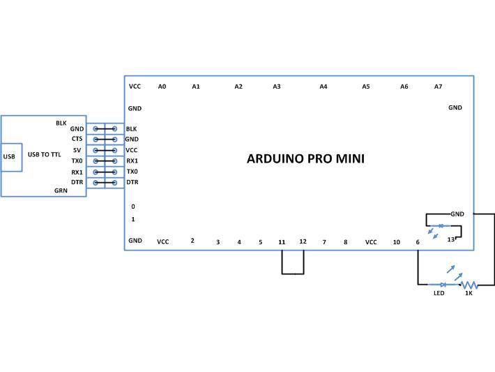
Since the arduino pro-mini board has no circuitary for interfacing it with the serial port or the USB port of the PC, an external USB to TTL converter board is required to connect it with the PC. This hardware helps in programming the arduino board and also helps in the serial communication with the PC through the USB port of the PC.
 External USB To TTL Converter Board For Programming Arduino And Serial Communication
Fig. 4: External USB to TTL converter board for programming Arduino and serial communication
 
It is assumed that the reader has gone through the project how to get started with the arduino and done all the things discussed in it.The code written for this project uses functions from the library <SPI.h> for initializing the SPI module and sending and receiving data using it. The functions namely SPI.begin() is used to initialize the SPI module and the function SPI.transfer() used to transfer a byte of data and receive a byte of data at the same time.
SPI.begin()
This function initializes the SPI module of the Arduino board and configures the corresponding digital I/O pins as SPI pins. The function always initializes the Arduino as SPI master device with the pin number 10 as SS, pin number 11 as MOSI, pin number 12 as MISO, and pin number 13 as SCK pin. The function has no parameters and it returns nothing.
SPI.transfer()
The function SPI.transfer() is used to transfer a byte of data to the slave device and to receive a byte of data from the slave device at the same time. The function takes a parameter which is the byte of data to be transmitted and the return from the function is a byte which is the data byte received from the slave device. Whenever only data transfer is required the return value can be ignored and whenever there is data to be read from the slave only the parameter passed to the function can be any arbitrary value.
The data transfer using the code is monitored in the Serial monitor window with the help of the serial communicating functions written in the code. The functions used in this projects are namely Serial.begin(), Serial.print(),Serial.println(), Serial.available(),Serial.read() and Serial.write(). The details of these functions and similar functions for the serial communication are already discussed in previous projects on how to do serial communication with the Arduino, how to send and receive serial data using arduino, how to do serial debugging with the Arduino. 
There is no slave device used in this project but the pin number 11 and 12 which are MOSI and MISO are shorted together so that whatever data send will be received at the same time. The function SPI.begin() is used to initialize the SPI module and the function SPI.transfer() is used to transfer bytes of a particular string and receive the same bytes which are then displayed in the Serial monitor using the serial communication functions.
When the coding is finished one can verify and upload the code to the Arduino board as explained in the project how to get started with the Arduino and observe the data bytes with the help of Serial monitor as explained in the project on how to do serial debugging with the Arduino.

Project Source Code

###


/*================================= EG LABS =======================================

Loop Back test for the SPI port of the Arduino


 The circuit:

 * LED attached from pin 6 to ground through a 1K resistor

================================== EG LABS =======================================*/


#include <SPI.h>                                                  // including the SPI library


char outByte [20] = "ENGINEERS GARAGE";                           // string to be send and received via SPI port

int led = 6;                                                      // variable which holds the pin number at which the LED is attached

char inByte;                                                      // variable which stores the value of the byte received from SPI bus

int i = 0;                                                         


void setup() 

{

  pinMode(led, OUTPUT);                                           // setting the LED pin as output

  Serial.begin(9600);                                             // initializing the serial port at 9600 baud rate

  SPI.begin();                                                    // initialize the SPI port as master

  delay(100);  

}


void loop() 

{    

  digitalWrite(led, HIGH);          

  for(i = 0; outByte [i] != ''; i ++)                            // send and receive the bytes of the string

  {

    inByte = SPI.transfer(outByte [i]);

    Serial.write(inByte);   

  }

  Serial.println();


  delay(1000);

  digitalWrite(led, LOW); 

  delay(1000);  

}

###


Circuit Diagrams

Circuit-Diagram-Testing-SPI-Module-Arduino

Project Components

  • Arduino Pro Mini
  • LED
  • Resistor

Project Video


Filed Under: Arduino Projects
Tagged With: Arduino, spi
 

Next Article

← Previous Article
Next Article →

Questions related to this article?
👉Ask and discuss on Electro-Tech-Online.com and EDAboard.com forums.


Tell Us What You Think!! Cancel reply

You must be logged in to post a comment.

EE TECH TOOLBOX

“ee
Tech Toolbox: Internet of Things
Explore practical strategies for minimizing attack surfaces, managing memory efficiently, and securing firmware. Download now to ensure your IoT implementations remain secure, efficient, and future-ready.

EE Learning Center

EE Learning Center
“engineers
EXPAND YOUR KNOWLEDGE AND STAY CONNECTED
Get the latest info on technologies, tools and strategies for EE professionals.

HAVE A QUESTION?

Have a technical question about an article or other engineering questions? Check out our engineering forums EDABoard.com and Electro-Tech-Online.com where you can get those questions asked and answered by your peers!


RSS EDABOARD.com Discussions

  • Multiple DC/DC converters and a single input source
  • Xiaomi Mijia 1C Robot problem of going backwards while working
  • Will this TL084C based current clamp circuit work?
  • ADS optimization cockpit window does not open
  • Voltage mode pushpull is a nonsense SMPS?

RSS Electro-Tech-Online.com Discussions

  • Parts required for a personal project
  • Curved lines in PCB design
  • Wideband matching an electrically short bowtie antenna; 50 ohm, 434 MHz
  • using a RTC in SF basic
  • PIC KIT 3 not able to program dsPIC

Featured – RPi Python Programming (27 Part)

  • RPi Python Programming 21: The SIM900A AT commands
  • RPi Python Programming 22: Calls & SMS using a SIM900A GSM-GPRS modem
  • RPi Python Programming 23: Interfacing a NEO-6MV2 GPS module with Raspberry Pi
  • RPi Python Programming 24: I2C explained
  • RPi Python Programming 25 – Synchronous serial communication in Raspberry Pi using I2C protocol
  • RPi Python Programming 26 – Interfacing ADXL345 accelerometer sensor with Raspberry Pi

Recent Articles

  • AC-DC power supply extends voltage range to 800 V DC
  • Infineon’s inductive sensor integrates coil system driver, signal conditioning circuits and DSP
  • Arm Cortex-M23 MCU delivers 87.5 µA/MHz active mode
  • STMicroelectronics releases automotive amplifiers with in-play open-load detection
  • Convection-cooled power controller integrates EtherCat connectivity

EE ENGINEERING TRAINING DAYS

engineering

Submit a Guest Post

submit a guest post
Engineers Garage
  • Analog IC TIps
  • Connector Tips
  • Battery Power Tips
  • DesignFast
  • EDABoard Forums
  • EE World Online
  • Electro-Tech-Online Forums
  • EV Engineering
  • Microcontroller Tips
  • Power Electronic Tips
  • Sensor Tips
  • Test and Measurement Tips
  • 5G Technology World
  • Subscribe to our newsletter
  • About Us
  • Contact Us
  • Advertise

Copyright © 2025 WTWH Media LLC. All Rights Reserved. The material on this site may not be reproduced, distributed, transmitted, cached or otherwise used, except with the prior written permission of WTWH Media
Privacy Policy

Search Engineers Garage

  • Electronic Projects & Tutorials
    • Electronic Projects
      • Arduino Projects
      • AVR
      • Raspberry pi
      • ESP8266
      • BeagleBone
      • 8051 Microcontroller
      • ARM
      • PIC Microcontroller
      • STM32
    • Tutorials
      • Audio Electronics
      • Battery Management
      • Brainwave
      • Electric Vehicles
      • EMI/EMC/RFI
      • Hardware Filters
      • IoT tutorials
      • Power Tutorials
      • Python
      • Sensors
      • USB
      • VHDL
    • Circuit Design
    • Project Videos
    • Components
  • Articles
    • Tech Articles
    • Insight
    • Invention Stories
    • How to
    • What Is
  • News
    • Electronic Product News
    • Business News
    • Company/Start-up News
    • DIY Reviews
    • Guest Post
  • Forums
    • EDABoard.com
    • Electro-Tech-Online
    • EG Forum Archive
  • DigiKey Store
    • Cables, Wires
    • Connectors, Interconnect
    • Discrete
    • Electromechanical
    • Embedded Computers
    • Enclosures, Hardware, Office
    • Integrated Circuits (ICs)
    • Isolators
    • LED/Optoelectronics
    • Passive
    • Power, Circuit Protection
    • Programmers
    • RF, Wireless
    • Semiconductors
    • Sensors, Transducers
    • Test Products
    • Tools
  • Learn
    • eBooks/Tech Tips
    • Design Guides
    • Learning Center
    • Tech Toolboxes
    • Webinars & Digital Events
  • Resources
    • Digital Issues
    • EE Training Days
    • LEAP Awards
    • Podcasts
    • Webinars / Digital Events
    • White Papers
    • Engineering Diversity & Inclusion
    • DesignFast
  • Guest Post Guidelines
  • Advertise
  • Subscribe