The system of satellites which helps in the positioning of a place on the surface of the earth is called Global Positioning System (GPS). The devices which can read the geographical coordinates of a place with the help of at least two to four GPS satellites are called GPS Receiver or simply GPS module. They can communicate with the other devices using serial communication protocols and hence they can be easily interfaced with microcontroller based systems.
The GPS module continuously produces a set of data regarding the position of the earth surface where it is situated which includes the current position with respect to the equator of the earth in terms of Latitude and Longitude. This data can be decoded and printed into the readable format with the help of a microcontroller. In this project the data regarding the geographical coordinate is extracted from the GPS output with the help of the Arduino and send it to a remote PC with the help of Xbee transceiver.
The Xbee is the brand name a wireless transceiver device which works on the ZigBee protocol. The Zigbee is the name of a wireless protocol maintained by the IEEE 802.15 standard. This is a protocol specified for wireless Personal Area Network (PAN) using low powered wireless transceivers. They can be used for simple point to point communication systems also.
They have an approximate range of 10 to 100 meters and are used in industries, scientific fields, medical fields etc. The Xbee module even though uses complex packet data based Zigbee protocol for communicating with each other, they can communicate with other devices using simplest serial communication protocol and hence they are widely used in microcontroller base boards.
The arduino board used in this project is the arduino pro-mini board and the IDE version of the arduino is 1.0.3 for windows. The image of the arduino pro-mini board and the arduino IDE are shown below: 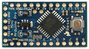
Fig. 2: Typical Arduino Pro-Mini Board
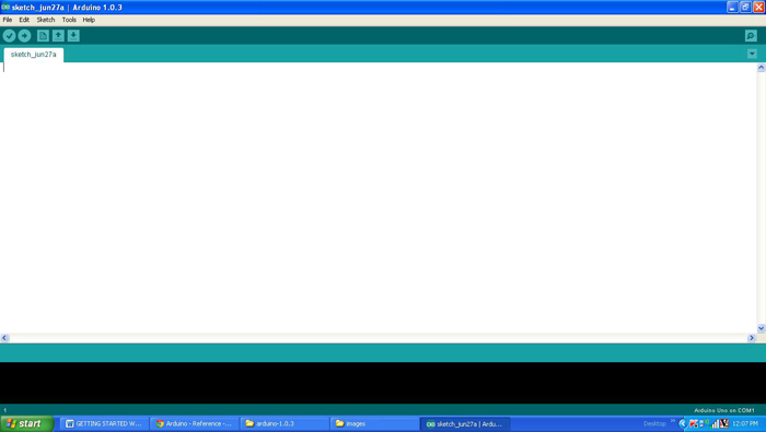
Fig. 3: Arduino IDE Software Window
Since the arduino pro-mini board has no circuitary for interfacing it with the serial port or the USB port of the PC, an external USB to TTL converter board is required to connect it with the PC. This hardware helps in programming the arduino board and also helps in the serial communication with the USB port of the PC.
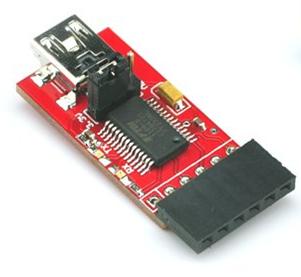
Fig. 4: External USB to TTL converter board for programming Arduino and serial communication
It is assumed that the reader has gone through the project how to get started with the arduino and tried out all the things discussed there.
Two Xbee S1 series transceivers modules are used in this project and the image of the same module shown in the following figure. Since the pitch of the pins of the modules are not breadboard compatible one can use the Xbee based design boards which comes with breadboard compatible pins.
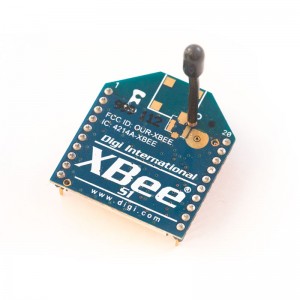
Fig. 5: Xbee S1 Series Transceiver Module
The Xbee modules have several digital and analog I/O pins apart from these pins and the pin out of an Xbee module is shown in the following table:
|
PIN |
DESCRIPTION |
|
1 |
Power Supply |
|
2 |
UART Data Out |
|
3 |
UART Data In |
|
4 |
Digital Output 8 (not supported as of 2/28/09) |
|
5 |
Module Reset (reset pulse must be at least 200 ns) |
|
6 |
PWM Output 0 / RX Signal Strength Indicator |
|
7 |
PWM Output 1 |
|
8 |
Do not connect |
|
9 |
DTR / Pin Sleep Control Line or Digital Input 8 |
|
10 |
Ground |
|
11 |
Analog Input 4 or Digital I/O 4 |
|
12 |
Clear-to-Send Flow Control or Digital I/O 7 |
|
13 |
Module Status Indicator |
|
14 |
Voltage Reference for A/D Inputs |
|
15 |
Associated Indicator, Analog Input 5 or Digital I/O 5 |
|
16 |
Request-to-Send Flow Control, Analog Input 6 or Digital I/O 6 |
|
17 |
Analog Input 3 or Digital I/O 3 |
|
18 |
Analog Input 2 or Digital I/O 2 |
|
19 |
Analog Input 1 or Digital I/O 1 |
|
20 |
Analog Input 0 or Digital I/O 0 |
Fig. 6: Pin Out Of Xbee Module
Since the Xbee modules communicate using serial communication protocol with the interfacing devices they can be connected to a microcontroller using a minimum of four pins, Power supply, and Ground, UART Data Out, and UART Data In pins. The pin number 2, UART Data Out is connected to the RX1 pin of the Arduino pro mini board and pin number 3 UART Data In is connected to the TX0 pin.
The GPS module used in this project is SR-91 based GPS module which can communicate the data regarding the current location to a PC or microcontroller through the serial port. The image of the GPS module used for this project is shown below:

Fig. 6: SR-91 based GPS Module for serial communication
The GPS send the data in standard NMEA format which consist of the real time data regarding the current position. The format includes so many sentences and among them one particular sentence referred to as “Global Positioning System Fix Data” is extracted to read the North East coordinate using the Arduino.
The screenshot of the “Global Positioning System Fix Data” among the NMEA format data output from the GPS module is shown in the following image:

Each sentence has a sentence identifier, actual data separated by commas and a check sum which has to be extracted to make it in readable format. The details of the sentence “Global Positioning System Fix Data” is given in the following table;
|
EXAMPLE DATA |
DESCRIPTION |
|
|
Sentence Identifier |
$GPGGA |
Global Positioning System Fix Data |
|
Time |
170834 |
17:08:34 Z |
|
Latitude |
4124.8963, N |
41d 24.8963′ N or 41d 24′ 54″ N |
|
Longitude |
08151.6838, W |
81d 51.6838′ W or 81d 51′ 41″ W |
|
Fix Quality: |
1 |
Data is from a GPS fix |
|
Number of Satellites |
05 |
5 Satellites are in view |
|
Horizontal Dilution of Precision (HDOP) |
1.5 |
Relative accuracy of horizontal position |
|
Altitude |
280.2, M |
280.2 meters above mean sea level |
|
Height of geoid above WGS84 ellipsoid |
-34.0, M |
-34.0 meters |
|
Time since last DGPS update |
blank |
No last update |
|
DGPS reference station id |
blank |
No station id |
|
Checksum |
*75 |
Used by program to check for transmission errors |
The implementation of the project which can receive the data from the GPS module and transmit the geographical coordinate extracted from the GPS data through Xbee is represented using the following block diagram:

Fig. 7: Block Diagram Of Transmiting GPS Data USing Arduino
The code written for this project on Arduino reads the serial data from the GPS module and writes the GPS data to the Xbee for transmission with the help of serial communication functions provided by the Arduino library. The functions like Serial.begin() which helps to initialize the serial port with a given baud rate, Serial.write() to send a data to the serial port, Serial.available() and Serial.read() functions to read data from the serial port are used in this project and they are already discussed in previous projects on how to do serial communication with the Arduino, how to send and receive serial data using arduino and how to do serial debugging with the Arduino.The method of getting the required latitude and longitude data from the NMEA format output from the GPS is explained in the previous project on how to interface GPS with Arduino .The method of interfacing a Xbee module and transmission of data using it is discussed in as previous project on how to interface Xbee module with Arduino.
When the coding is finished one can verify and upload the code to the Arduino board as explained in the project how to get started with the Arduino. As soon as the board is powered up the Xbee in the Arduino board automatically establishes communication with another Xbee which is connected to the serial port of a PC. The second Xbee board can be connected to the PC using the same USB to TTL converter board which has been used to program the Arduino board. The geographical coordinates can be then be read using any serial monitoring software or using the Arduino IDE’s serial monitoring software itself as explained in the project how to do serial debugging with the Arduino.
Project Source Code
### /*============================ EG LABS ===================================// Demonstration on how to use GPS and XBEE with an arduino board The circuit: LCD: * LCD RS pin to digital pin 12 * LCD Enable pin to digital pin 11 * LCD D4 pin to digital pin 7 * LCD D5 pin to digital pin 6 * LCD D6 pin to digital pin 5 * LCD D7 pin to digital pin 4 * LCD R/W pin to ground * 10K resistor: * ends to +5V and ground * wiper to LCD pin 3 * LED anode attached to digital output 9 * LED cathode attached to ground through a 1K resistor XBEE: RX PIN OF XBEE TO TX0 PIN OF ARDUINO TX PIN OF XBEE TO RX1 PIN OF ARDUINO SHORT THE GROUND PINS OF ARDUINO, XBEE AND GPS ============================== EG LABS ===================================*/ #include <LiquidCrystal.h> // initialize the library with the numbers of the interface pins LiquidCrystal lcd(12, 11, 7, 6, 5, 4); // give the pin a name: int led = 9; // incoming serial byte int inByte = 0; int east [ 15 ]; int north [ 15 ]; int i; void setup() { // set up the lcd's number of columns and rows: lcd.begin(16, 2); lcd.print("ENGINEERS GARAGE"); lcd.setCursor(0, 1); lcd.print(" GPS + XBEE "); // initialize the led pin as an output. pinMode(led, OUTPUT); } void loop () { Serial.begin(4800); delay(100); //==================== searching for "GG" ===================// do { do { while ( !Serial.available() ); } while ( 'G' != Serial.read() ); while(!Serial.available()); } while ( 'G' != Serial.read() ); //==================== searching for "GG" ===================// //============== seeking for north cordinate ==============// do { while ( !Serial.available() ); } while ( ',' != Serial.read() ); do { while ( !Serial.available() ); } while ( ',' != Serial.read() ); //============== seeking for north cordinate ==============// //============== printing the north cordinate ===============// // Serial.print(" N: "); i = 0; do { while ( !Serial.available() ); inByte = Serial.read(); north [ i ] = inByte; // Serial.write ( inByte ); i ++; } while ( ',' != inByte ); //============== printing the north cordinate ===============// //============== seeking for east cordinate ==============// do { while ( !Serial.available() ); } while ( ',' != Serial.read() ); //============== seeking for east cordinate ==============// //============== printing the east cordinate ===============// // Serial.print(" E: "); i = 0; do { while ( !Serial.available() ); inByte = Serial.read(); east [ i ] = inByte; i ++; // Serial.write ( inByte ); } while ( ',' != inByte ); //============== printing the east cordinate ===============// delay(500); digitalWrite(led, HIGH); Serial.begin(9600); delay(100); // send the initial data once // Serial.print('n'); Serial.print(" EG LABS "); Serial.print('n'); Serial.print('r'); Serial.print(" GEOGRAPHICAL CORDINATES"); Serial.print('n'); Serial.print('r'); Serial.print('n'); Serial.print( " N: " ); for ( i = 0; north [ i ] != '�'; i ++ ) Serial.write ( north [ i ] ); Serial.print( " E: " ); for ( i = 0; east [ i ] != '�'; i ++ ) Serial.write ( east [ i ] ); Serial.println(); delay ( 500 ); digitalWrite(led, LOW); } ###
Circuit Diagrams
Project Components
Project Video
Filed Under: Arduino
Filed Under: Arduino

Questions related to this article?
👉Ask and discuss on Electro-Tech-Online.com and EDAboard.com forums.
Tell Us What You Think!!
You must be logged in to post a comment.