Engineers Garage

  • Electronic Projects & Tutorials
    • Electronic Projects
      • Arduino Projects
      • AVR
      • Raspberry pi
      • ESP8266
      • BeagleBone
      • 8051 Microcontroller
      • ARM
      • PIC Microcontroller
      • STM32
    • Tutorials
      • Audio Electronics
      • Battery Management
      • Brainwave
      • Electric Vehicles
      • EMI/EMC/RFI
      • Hardware Filters
      • IoT tutorials
      • Power Tutorials
      • Python
      • Sensors
      • USB
      • VHDL
    • Circuit Design
    • Project Videos
    • Components
  • Articles
    • Tech Articles
    • Insight
    • Invention Stories
    • How to
    • What Is
  • News
    • Electronic Product News
    • Business News
    • Company/Start-up News
    • DIY Reviews
    • Guest Post
  • Forums
    • EDABoard.com
    • Electro-Tech-Online
    • EG Forum Archive
  • DigiKey Store
    • Cables, Wires
    • Connectors, Interconnect
    • Discrete
    • Electromechanical
    • Embedded Computers
    • Enclosures, Hardware, Office
    • Integrated Circuits (ICs)
    • Isolators
    • LED/Optoelectronics
    • Passive
    • Power, Circuit Protection
    • Programmers
    • RF, Wireless
    • Semiconductors
    • Sensors, Transducers
    • Test Products
    • Tools
  • Learn
    • eBooks/Tech Tips
    • Design Guides
    • Learning Center
    • Tech Toolboxes
    • Webinars & Digital Events
  • Resources
    • Digital Issues
    • EE Training Days
    • LEAP Awards
    • Podcasts
    • Webinars / Digital Events
    • White Papers
    • Engineering Diversity & Inclusion
    • DesignFast
  • Guest Post Guidelines
  • Advertise
  • Subscribe

How to use a boost converter with a Li-ion battery and BL8530 IC

By Ayush Jain June 3, 2024

A major advantage of a switching regulator is that it can boost a lower voltage into a higher one. This type of regulator is also known as a boost or step-up converter.

A boost converter is used to step up an input voltage to a higher level as required by a load. This capability is typically achieved by storing energy in an inductor and releasing it to the load at a higher voltage.

Objective
This project aims to boost a 3.3V Lithium-ion (Li-on) battery up to 5 volts, the standard voltage used by many devices. 

To step up a 3.3V Li-on to 5Vs, we’ll employ a BL8530 integrated circuit (IC), which is a boost converter IC. The converter’s input voltage can be between 0.8V and Vout, providing 2.5 to 6V at the output.  

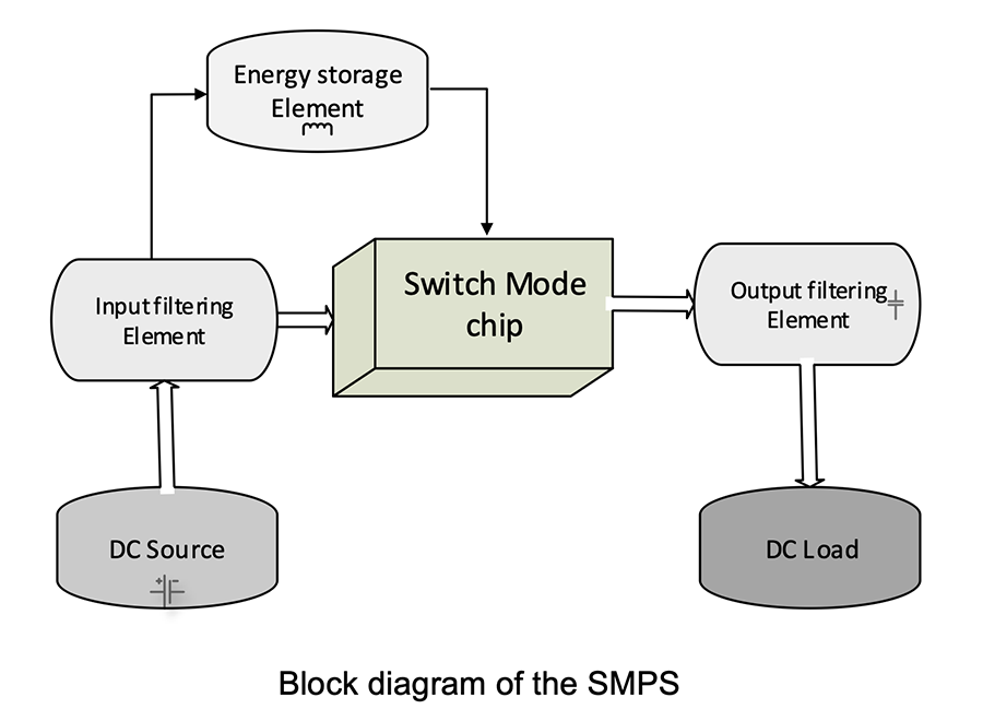
This design can include various blocks, with built in the Switch Mode IC and other added externally.

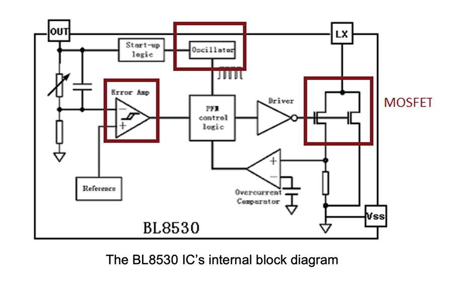
Below is the BL8530 IC’s internal block diagram. It consists of a MOSFET, used as a switch, and an oscillator to generate the PWM signal. An error amplifier maintains the regulated voltage at the output.

Working principle
The boost converter works on the principle of a switching mechanism, which reduces much of the power during the step-up process.

The converter requires an inductor, diode, transistor, capacitor, and oscillator to boost the input voltage.

During the PWM’s ON period, the inductor stores energy through the transistor and the capacitor provides the output. During the OFF period, the inductor losses its energy through the diode and provides the output voltage.
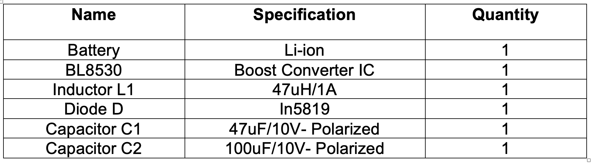
Components
You’ll need the below components to design the power supply.
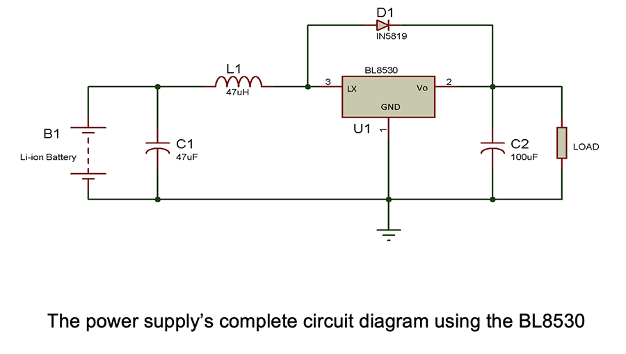
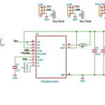

Schematic

External components
The BL8530 IC requires an inductor, diode, and capacitor to boost the input voltage. Here are some basic parameters for selecting the components…

1. The input and output capacitor. If the power supply is positioned near the IC, there’s no need for an input capacitor. However, an input capacitor greater than 10uF supports stability and removes any voltage spikes at the input line. 

An output capacitor of about 100uF is recommended for this project. Anything above this will slow down the response and is only helpful when there’s a larger current output.

2. The inductor. The below equation can be used for the inductor calculation. 

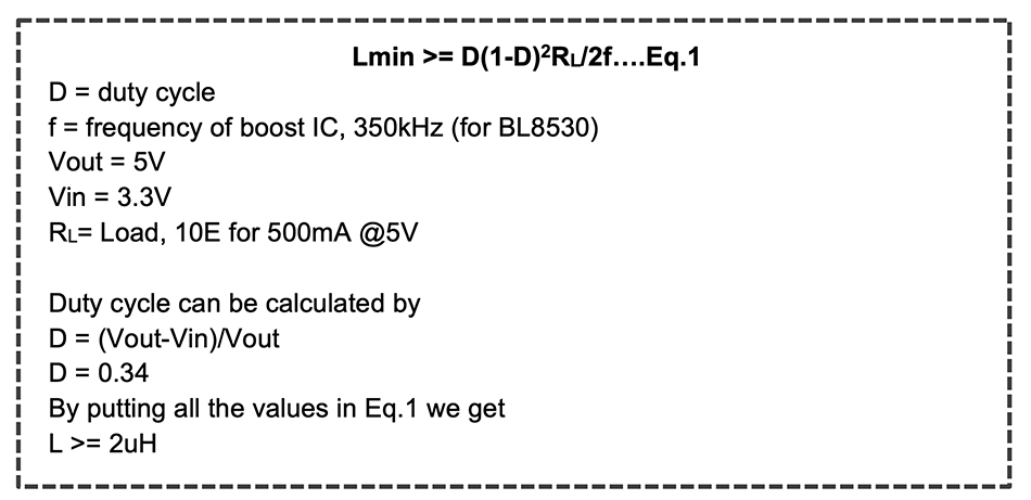
Note: the actual inductor value is more than this since we need to account for the ESR of the inductor, the capacitor, and the dropout voltage of the diode. 

If the inductor is less than Lmin, it will affect the efficiency and stability of the circuit.

Size considerations
An inductor with a small value can provide a large output current, but it will also be less efficient. An inductor with a larger value can be used to improve efficiency. 

So, a small inductor can offer the best results if the circuit is supposed to provide a large output current at a low input voltage.

As per the BL8530’s datasheet, a 47uH inductor is ideal in all applications.

3. The diode. The diode will affect the efficiency of the overall system. A general rectifier diode can perform well in a low load. A Schottky diode is recommended for a high load, such as the 1N5819 or 1N5822, etc. 

The suggested values for this project are:

  • Inductor- 10uH – 100uH
  • Output capacitor- 47uF- 220uF
  • Input capacitor > 10uF
  • Diode – Schottky 

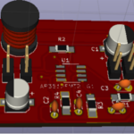
Designing the circuit
The above equation gives the minimum value of the inductor, but not its actual value. If we use this minimum value in the design, the circuit will become unstable.

For our project, we based our calculations on the 2uH inductor. But during testing, we noted that a 4.7uH inductor failed to provide the desired results, leaving the circuit unstable. We decided to use the 47uH inductor as per the datasheet of the IC. This works well in our design.

Practical observation:
Vout (no load) = 5.07V

Efficiency
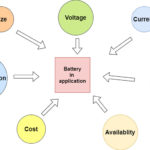
The efficiency defines the power loss in the circuit. Lesser efficiency led to greater power loss and vice-versa. Power loss indirectly affects the system’s cost. It’s worth calculating the system’s efficiency if using a battery as the power source or if the circuit will be in use for a long period. It can be used to estimate the cost of the system. 

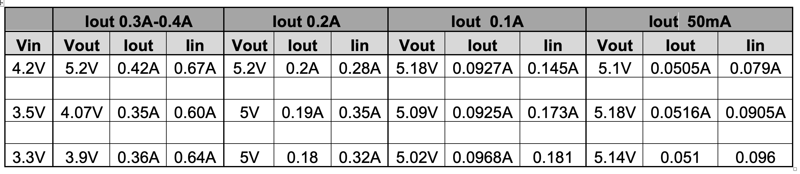
By using the below equation below, it’s possible to calculate the efficiency…

E% = (Vout*Iout)*100/(Vin*Iin)

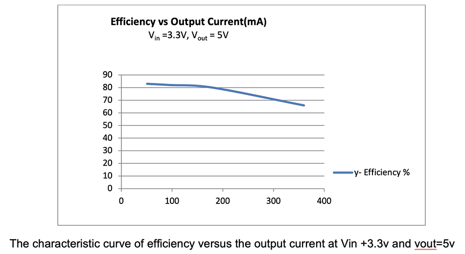
Characteristic curve

Thermal management
Every electronic system dissipates power in the form of heat, so it’s advisable to include a heat sink in the power supply circuit.

Performance
1.
The circuit provides excellent voltage regulation for loads under 200mA
2. An efficiency of 70-80% is expected, given the above results 

Project advantages

  • Requires only a few components
  • Is economical and a small size
  • Can be used with digital circuits
  • Li-ion or Duracell batteries can provide the power source
  • Can be used in electronic toys or LED applications

Precautions
1.
Use the recommended inductor and capacitor for good efficiency.
2. The circuit’s capacitor must have a higher voltage rating than the input supply voltage. Otherwise, the capacitor will leak current due to the excess voltage at its plates, and it will burst.
3. Ensure all capacitors are discharged before working on the DC power supply.
4. The current rating of the inductor should be 1.15 times greater than the output current.


You may also like:

  • battery types
    What are the different battery types for specific applications?

  • How to use a buck-boost converter to regulate a Li-ion…

  • How to design a DC-to-DC buck converter

  • Designing a Switched Mode Power Supply (SMPS)

  • How do dc-dc converters work?

Filed Under: Tutorials
Tagged With: batteries, bl8530, boostconverter, converters, ic, integratedcircuit, lithiumion, lithiumionbatteries, smps, switchingregulator, voltage
 

Next Article

← Previous Article
Next Article →

Questions related to this article?
👉Ask and discuss on Electro-Tech-Online.com and EDAboard.com forums.


Tell Us What You Think!! Cancel reply

You must be logged in to post a comment.

EE TECH TOOLBOX

“ee
Tech Toolbox: Internet of Things
Explore practical strategies for minimizing attack surfaces, managing memory efficiently, and securing firmware. Download now to ensure your IoT implementations remain secure, efficient, and future-ready.

EE Learning Center

EE Learning Center
“engineers
EXPAND YOUR KNOWLEDGE AND STAY CONNECTED
Get the latest info on technologies, tools and strategies for EE professionals.

HAVE A QUESTION?

Have a technical question about an article or other engineering questions? Check out our engineering forums EDABoard.com and Electro-Tech-Online.com where you can get those questions asked and answered by your peers!


RSS EDABOARD.com Discussions

  • Multiple DC/DC converters and a single input source
  • Voltage mode pushpull is a nonsense SMPS?
  • High Side current sensing
  • Reducing "shoot-through" in offline Full Bridge SMPS?
  • MOSFET thermal noise in Weak vs Strong inversion

RSS Electro-Tech-Online.com Discussions

  • Failure of polypropylene motor-run capacitors
  • Siemens large industrial PLC parts
  • Wideband matching an electrically short bowtie antenna; 50 ohm, 434 MHz
  • Curved lines in PCB design
  • using a RTC in SF basic

Featured – RPi Python Programming (27 Part)

  • RPi Python Programming 21: The SIM900A AT commands
  • RPi Python Programming 22: Calls & SMS using a SIM900A GSM-GPRS modem
  • RPi Python Programming 23: Interfacing a NEO-6MV2 GPS module with Raspberry Pi
  • RPi Python Programming 24: I2C explained
  • RPi Python Programming 25 – Synchronous serial communication in Raspberry Pi using I2C protocol
  • RPi Python Programming 26 – Interfacing ADXL345 accelerometer sensor with Raspberry Pi

Recent Articles

  • What is AWS IoT Core and when should you use it?
  • AC-DC power supply extends voltage range to 800 V DC
  • Infineon’s inductive sensor integrates coil system driver, signal conditioning circuits and DSP
  • Arm Cortex-M23 MCU delivers 87.5 µA/MHz active mode
  • STMicroelectronics releases automotive amplifiers with in-play open-load detection

EE ENGINEERING TRAINING DAYS

engineering

Submit a Guest Post

submit a guest post
Engineers Garage
  • Analog IC TIps
  • Connector Tips
  • Battery Power Tips
  • DesignFast
  • EDABoard Forums
  • EE World Online
  • Electro-Tech-Online Forums
  • EV Engineering
  • Microcontroller Tips
  • Power Electronic Tips
  • Sensor Tips
  • Test and Measurement Tips
  • 5G Technology World
  • Subscribe to our newsletter
  • About Us
  • Contact Us
  • Advertise

Copyright © 2025 WTWH Media LLC. All Rights Reserved. The material on this site may not be reproduced, distributed, transmitted, cached or otherwise used, except with the prior written permission of WTWH Media
Privacy Policy

Search Engineers Garage

  • Electronic Projects & Tutorials
    • Electronic Projects
      • Arduino Projects
      • AVR
      • Raspberry pi
      • ESP8266
      • BeagleBone
      • 8051 Microcontroller
      • ARM
      • PIC Microcontroller
      • STM32
    • Tutorials
      • Audio Electronics
      • Battery Management
      • Brainwave
      • Electric Vehicles
      • EMI/EMC/RFI
      • Hardware Filters
      • IoT tutorials
      • Power Tutorials
      • Python
      • Sensors
      • USB
      • VHDL
    • Circuit Design
    • Project Videos
    • Components
  • Articles
    • Tech Articles
    • Insight
    • Invention Stories
    • How to
    • What Is
  • News
    • Electronic Product News
    • Business News
    • Company/Start-up News
    • DIY Reviews
    • Guest Post
  • Forums
    • EDABoard.com
    • Electro-Tech-Online
    • EG Forum Archive
  • DigiKey Store
    • Cables, Wires
    • Connectors, Interconnect
    • Discrete
    • Electromechanical
    • Embedded Computers
    • Enclosures, Hardware, Office
    • Integrated Circuits (ICs)
    • Isolators
    • LED/Optoelectronics
    • Passive
    • Power, Circuit Protection
    • Programmers
    • RF, Wireless
    • Semiconductors
    • Sensors, Transducers
    • Test Products
    • Tools
  • Learn
    • eBooks/Tech Tips
    • Design Guides
    • Learning Center
    • Tech Toolboxes
    • Webinars & Digital Events
  • Resources
    • Digital Issues
    • EE Training Days
    • LEAP Awards
    • Podcasts
    • Webinars / Digital Events
    • White Papers
    • Engineering Diversity & Inclusion
    • DesignFast
  • Guest Post Guidelines
  • Advertise
  • Subscribe