LiDAR, or “light detection and ranging,” is a remote-sensing method that uses light in laser form to measure distances or ranges. LiDAR has been used for decades although there are more recent advancements in the technology.
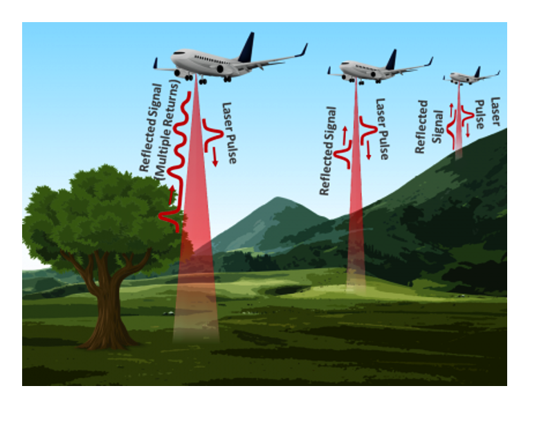
These include laser scanning and processing speeds that make 3D mapping possible and accessible. This technique uses light (precise laser pulses) to map an underlying object or the terrain (the earth’s surface). The laser is pointed on an object’s surface or the terrain and, after hitting the surface, reflects back.
Mapping and 3D drawings of an object’s surface or terrain is quite simple. Every reflection of light is composed of thousands of individual beams. These beams, or patterns, vary in distance — each one is nearly 10 cm apart. A scanner picks these up.
The time and distance it takes for these beams to occur are recorded by the scanner. Additionally, the distance between the object and the light source is calculated by using the recorded time and speed of light.
If we place dots representing each beam at its distance and then view these dots from the opposite axis, it’s possible to see a 3D image of the ground. Let’s check out this phenomenon in an image.
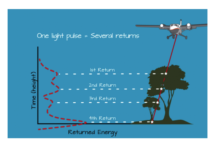
Each reflected beam depicts a dot in 3D space. For each object, the beams will be different. For example, in the image below, you’ll note the differences between the ground, a hill, and a tree.
For this project, we’re going to use a LiDAR sensor offered by SparkFun Electronics. SparkFun provides a pre-defined Arduino library for the sensor, which is ideal. The company offers two variants of LiDAR (that are distinguished based on updated speed bases).
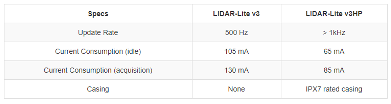
The LIDAR-Lite v3HP a compact, high-performance optical distance measurement sensor from Garmin. The v3HP is similar in function to that of the v3 but can sample faster at rates (almost double!). Another improvement is that this v3HP model is more efficient in terms of its its current consumption rates.
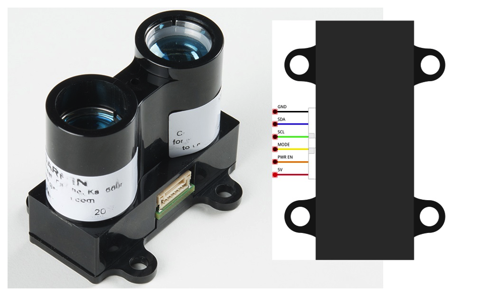
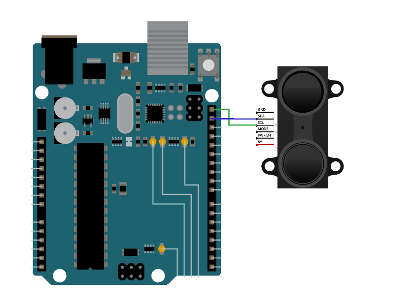
The LIDAR-Lite v3HP has six pins. Communication with an external controller is possible via the I2C protocol with a pulse-width modulation (PWM) output. For the I2C, the SDA (data) and SCL (clock) pins are used. For the PWM, the “Mode” pin is inserted, which places the sensor in analog output mode.
Now, each distance corresponds to an analog output value that must be sampled by the analog-to-digital converter (ADC) at the host side. We’ll grab the data using the I2C protocol.
The circuit diagram for this project is simple. Simply connect the sensor’s I2C wires with Arduino’s I2C pins, which are located at A4 and A5. They’re are also present at the top of the header on the right side.
Circuit diagram
The code
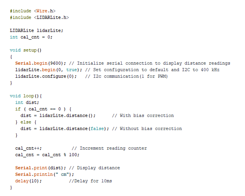
To begin, we included the I2C general library (wire.h) in Arduino sketch, followed by the LiDARLite library from SparkFun. So, an instance of the LiDARLite library is created.
In the setup function, we then initialized the serial monitor and started it at 9600 bits per second, and defined the I2C as a communication protocol.
The loop function is where we measure the distance. Two different functions are executed on the basis of the condition: one function calculates distance without bias and the other uses bias. The sensor’s calibration is done in the function without bias.
The calculated distance is displayed on Arduino’s serial monitor. A 10ms delay is used after every scan to prevent any crossover or collisions.
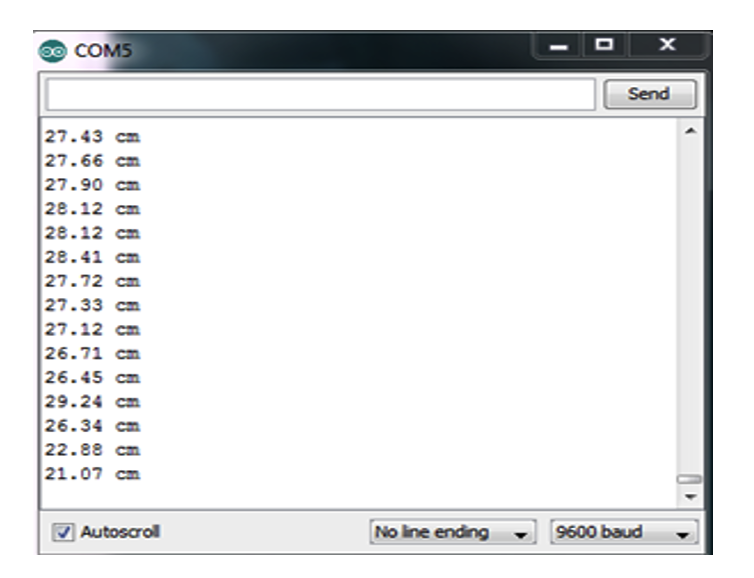
The data is displayed on the LCD’s serial monitor. If we point this data on a 2D platform, we’ll get something like this…
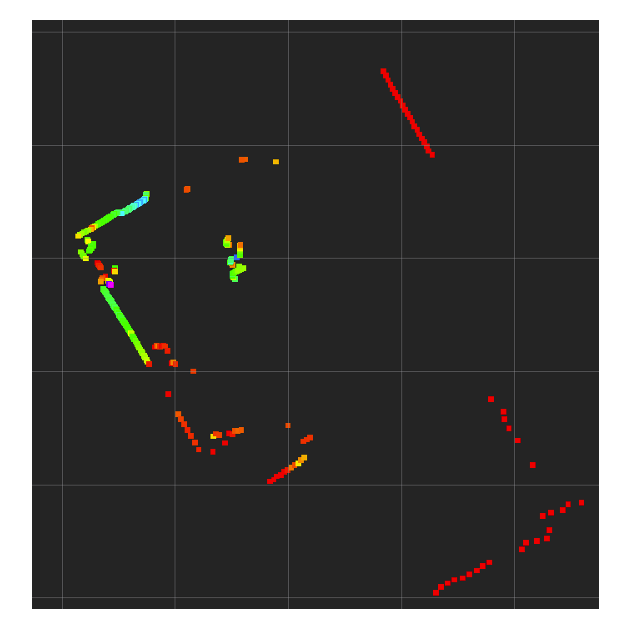
A 360-degree view of a 2D space, depicting obstacles and the distance from the sensor.
We can classify objects with the help of dots. To do so, however, a LiDAR that can scan an entire area from a center point is required. With the SparkFun LiDAR used here, it’s only possible to calculate distances.
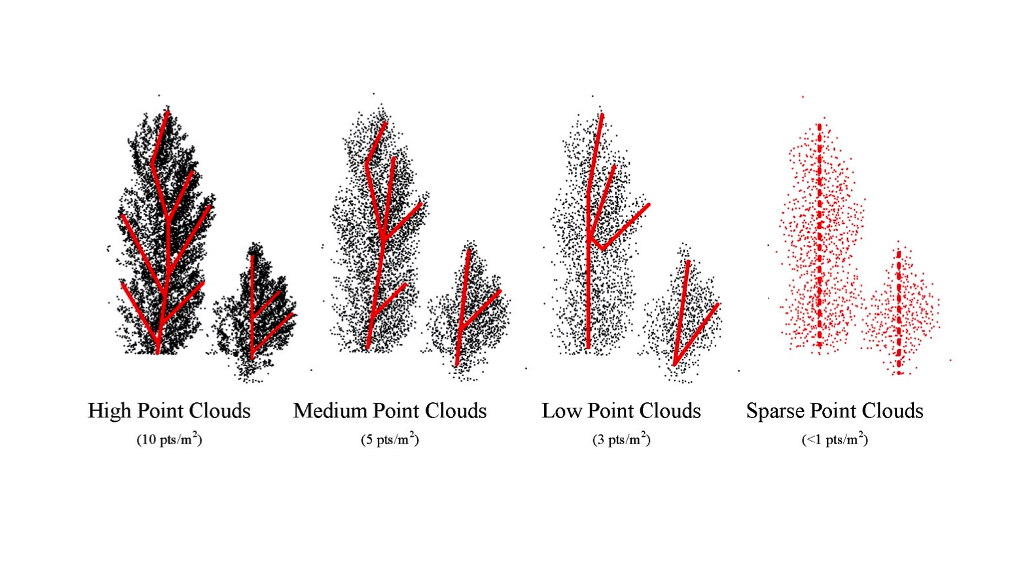
Higher-resolution LiDARS can also calculate the angle of light from a reference point — the angles and distances based on the terrain are then 3D representations. For example, look at the below images of trees in front of a LiDAR sensor.
From a set reference point, the distance and angle of the light are grouped together. If only the distance is known, then the dots are a horizontal straight line.
Unfortunately, small-scale, do-it-yourself LiDARs simply aren’t powerful enough to support angle calculation.
Where to purchase the parts?
Image sources:
You may also like:


Filed Under: Microcontroller Projects

Questions related to this article?
👉Ask and discuss on Electro-Tech-Online.com and EDAboard.com forums.
Tell Us What You Think!!
You must be logged in to post a comment.