Engineers Garage

  • Electronics Projects and Tutorials
    • Electronic Projects
      • Arduino Projects
      • AVR
      • Raspberry pi
      • ESP8266
      • BeagleBone
      • 8051 Microcontroller
      • ARM
      • PIC Microcontroller
      • STM32
    • Tutorials
      • Audio Electronics
      • Battery Management
      • Brainwave
      • Electric Vehicles
      • EMI/EMC/RFI
      • Hardware Filters
      • IoT tutorials
      • Power Tutorials
      • Python
      • Sensors
      • USB
      • VHDL
    • Circuit Design
    • Project Videos
    • Components
  • Articles
    • Tech Articles
    • Insight
    • Invention Stories
    • How to
    • What Is
  • News
    • Electronic Product News
    • Business News
    • Company/Start-up News
    • DIY Reviews
    • Guest Post
  • Forums
    • EDABoard.com
    • Electro-Tech-Online
    • EG Forum Archive
  • DigiKey Store
    • Cables, Wires
    • Connectors, Interconnect
    • Discrete
    • Electromechanical
    • Embedded Computers
    • Enclosures, Hardware, Office
    • Integrated Circuits (ICs)
    • Isolators
    • LED/Optoelectronics
    • Passive
    • Power, Circuit Protection
    • Programmers
    • RF, Wireless
    • Semiconductors
    • Sensors, Transducers
    • Test Products
    • Tools
  • Learn
    • eBooks/Tech Tips
    • Design Guides
    • Learning Center
    • Tech Toolboxes
    • Webinars & Digital Events
  • Resources
    • Digital Issues
    • EE Training Days
    • LEAP Awards
    • Podcasts
    • Webinars / Digital Events
    • White Papers
    • Engineering Diversity & Inclusion
    • DesignFast
  • Guest Post Guidelines
  • Advertise
  • Subscribe

How to Use Arduino to Display Sensor Values on LCD- (Part 14/49)

By Ajish Alfred July 1, 2013

The LCD module makes an embedded system completely independent with which can take analog or digital input on its input pins and display the corresponding output in its own screen along with generating other kind of outputs. The LCD modules comes in different sizes varies from single line monochrome display to large graphical color display all of them using almost same method for displaying data. The Arduino can be used as a stand-alone board of which the output or inputs can be taken from the boards or given to the board. The Arduino board even though has various kinds of communication ports they can’t match with the effectiveness provided by the LCD module. Moreover the LCD module eliminates the requirement for having a PC or any other kind of devices connected with the Arduino board to display the data send by the board.

Since the basic Arduino board does not have a built–in LCD module to display data one should connect it externally to display data like strings, sensor values etc. The libraries in the Arduino IDE helps in accessing the LCD module very easily. This project demonstrates how to use a 16x2 LCD with the Arduino board for displaying a sensor value continuously. The code has been written using the library functions and the sensor used here is a simple potentiometer which can vary its voltage in its variable pin. 


The Arduino board has all the required circuitary to get the built-in AVR microcontroller running. It has also pins which can be configure as digital output only, digital or analog output, digital input only and digital or analog input. Any AVR microcontroller based board which follows the standard Arduino schematic and is flashed with the Arduino bootloader can be called an Arduino board. The Arduino IDE is also very simple that anyone who have basic knowledge of c programming can quickly get started with it. The tutorial on Getting started with the Arduino explains about the steps required to get start with an Arduino board.

The Arduino board used in this project is the Arduino pro-mini board and the IDE version of the Arduino is 1.0.3 for windows. The image of the Arduino pro-mini board and the Arduino IDE are shown below;
 Typical Arduino Pro-Mini Board
Fig. 2: Typical Arduino Pro-Mini Board
 
Arduino IDE Software Window
Fig. 3: Arduino IDE Software Window
 
Since the Arduino pro-mini board has no circuitary for interfacing it with the serial port or the USB port of the PC, an external USB to TTL converter board is required to connect it with the PC. This hardware helps in programming the Arduino board and also helps in the serial communication with the USB port of the PC.
 External USB To TTL Converter Board For Programming Arduino And Serial Communication
Fig. 4: External USB to TTL converter board for programming Arduino and serial communication
It is assumed that the reader has gone through the project how to get started with the Arduino and tried out all the things discussed there.
A previous project on how to use analog input and output of the Arduino discusses about how to use analog input /output channels of the Arduino board to read analog values and to write analog values. Another project explains how it is possible to debug the values which are received by the Arduino board and which the Arduino board write to the external pin so as to generate a voltage.The variable pin of a potentiometer is connected to the analog pin;in this project the pin A0. The other two pins of the potentiometer is connected to the VCC and GND so that as the variable moves it can divide the entire supply voltage and provide it as the analog input voltage for the Arduino board. An LED is connected to the analog output pin through a current limiting resistor; in this project it is connected to the pin 6. The code continuously reads the value from the potentiometer and writes the corresponding value to change the brightness of the LED connected to the pin 6.
The code written for this project make use of the analog read and write functions like analogRead() andanalogWrite() etc. It also uses library functions which help to access the LCD module like lcd.begin(), and lcd.print() . These functions for accessing the LCD are available in the header file <LiquidCrystal.h>. The details of the analog read and write functions are explained in a previous project on how to use analog input and output of the Arduino. The functions for interfacing the LCD are discussed in the previous project on how to interface 16*2 LCD with the Arduino board.
In this particular project one more function from the <LiquidCrystal.h> is used which is not there in the previous project and is discussed below.


lcd.setCursor()


The lcd.setCursor() function is used to set the position of the cursor in the LCD screen in such a way that the subsequent letters will be displayed from that particular position only. The function has two parameters and the first one represents the column number and the second one represents the row number. The row and column number starts with zero and the maximum value depend on the type of LCD used.
The lcd.setCursor() can be used to set the cursor at a particular position of the LCD screen as shown in the following statement;
lcd.setCursor(7,0);
The above statement will set the cursor at the 8th position of the first line of an LCD screen and further display will happen from that position onwards.
THE CODE
The code initializes the 16*2 LCD using the function lcd.begin() after initializing the library using the function LiquidCrystallcd(). The analog value is read from the analog input pin using the function analogRead() and is then mapped from 10 bit mode to 8 bit mode using the function map(). The value is thgen multiplied by 5 and is divided by 255 to get the 5V equivalent of that value.  The lcd.print() function is then used to print the value after setting the cursor using lcd.setCursor() function.
// include the library code:
#include <LiquidCrystal.h>
// initialize the library with the numbers of the interface pins
LiquidCrystallcd(12, 11, 5, 4, 3, 2);
constintanalogInPin = A0;  // Analog input pin that the potentiometer is attached to
constintanalogOutPin = 6;  // Analog output pin that the LED is attached to
intpotvalue = 0;
intoutputvalue=0;
void setup()
{
  // set up the LCD’s number of columns and rows:
lcd.begin(16, 2);
lcd.print(“ENGINEERS GARAGE”);
}
void loop()
{
  // read the analog in value:
potvalue = analogRead(analogInPin);       
 // map it to the range of the analog out:
outputvalue = map(potvalue, 0, 1023, 0, 255);
lcd.setCursor(7, 2);
lcd.print((outputvalue * 5)/255);
lcd.print(“V”);
  // change the analog out value:
analogWrite(analogOutPin, outputvalue);     
delay(100)  ;   
}
The code also glows an LED with the brightness which is equivalent to the value read from the analog input pin as discusses in a previous project on how to use analog input and output of the Arduino.
Once done with the coding one can verify and upload the code to the Arduino board as explained in the project how to get started with the Arduino and the brightness of the LED can be observed to vary as the variable of the potentiometer moves. The voltage read from the analog input pin will be displayed in the LCD along with varying the brightness of the LED.

Project Source Code

###


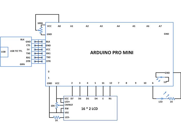
 /*============================EG LABS ===================================//
Demonstration on how to use 16*2 LCD with an arduino board
The circuit:
LCD:
* LCD RS pin to digital pin 12
* LCD Enable pin to digital pin 11
* LCD D4 pin to digital pin 5
* LCD D5 pin to digital pin 4
* LCD D6 pin to digital pin 3
* LCD D7 pin to digital pin 2
* LCD R/W pin to ground
* 10K resistor:
* ends to +5V and ground
* wiper to LCD pin 3
* LED anode attached to digital output 6
* LED cathode attached to ground through a 1K resistor
Analog input:
 * Potentiometer attached to analog input A0
 * one side pin (either one) to ground
 * the other side pin to +5V
 * LED anode (long leg) attached to digital output 6
 * LED cathode (short leg) attached to ground through a 1K resistor
//============================ EG LABS ===================================*/
//include the library code:
#include <LiquidCrystal.h> //initialize the library with the numbers of the interface pins
LiquidCrystal lcd(12, 11, 5, 4, 3, 2);
const int analogInPin = A0;  // Analog input pin that the potentiometer is attached to
const int analogOutPin = 6;  // Analog output pin that the LED is attached to
intpotvalue = 0;
intoutputvalue=0;
void setup()
{
  // set up the LCD's number of columns and rows:
  lcd.begin(16, 2);
  lcd.print("ENGINEERS GARAGE");
}
void loop()
{
  // read the analog in value:
  potvalue = analogRead(analogInPin);  // map it to the range of the analog out:
  outputvalue = map(potvalue, 0, 1023, 0, 255);
  lcd.setCursor(7, 2);
  lcd.print((outputvalue * 5)/255);
  lcd.print("V"); // change the analog out value:
  analogWrite(analogOutPin, outputvalue);     
  delay(100) ;   
}

###


Circuit Diagrams

Circuit-Diagram-Using-Arduino-Display-Sensor-Values-LCD

Project Components

  • Arduino Pro Mini
  • LCD
  • LED
  • Resistor

Project Video


Filed Under: Arduino Projects
Tagged With: Arduino, lcd
 

Next Article

← Previous Article
Next Article →

Questions related to this article?
👉Ask and discuss on EDAboard.com and Electro-Tech-Online.com forums.


Tell Us What You Think!! Cancel reply

You must be logged in to post a comment.

EE TECH TOOLBOX

“ee
Tech Toolbox: Internet of Things
Explore practical strategies for minimizing attack surfaces, managing memory efficiently, and securing firmware. Download now to ensure your IoT implementations remain secure, efficient, and future-ready.

EE Learning Center

EE Learning Center
“engineers
EXPAND YOUR KNOWLEDGE AND STAY CONNECTED
Get the latest info on technologies, tools and strategies for EE professionals.

HAVE A QUESTION?

Have a technical question about an article or other engineering questions? Check out our engineering forums EDABoard.com and Electro-Tech-Online.com where you can get those questions asked and answered by your peers!


RSS EDABOARD.com Discussions

  • Estimating Power Budget with Limited Datasheet Information
  • RFsoc4x2 fpga diagram request
  • GanFet power switch starts burning after 20 sec
  • 12VAC to 12VDC 5A on 250ft 12AWG
  • Unity Gain Buffer with 0 to 0.5V Range

RSS Electro-Tech-Online.com Discussions

  • An Update On Tarrifs
  • Trying to use a L9110s motor driver chip
  • I want to make a CRT with some modifications But i have no Idea where to start
  • Funny Images Thread!
  • Need Help Figuring Out the Schematics Of Circuit Board

Featured – Designing of Audio Amplifiers part 9 series

  • Basics of Audio Amplifier – 1/9
  • Designing 250 Milli Watt Audio Power Amplifier – 2/9
  • Designing 1 Watt Audio Power Amplifier – 3/9
  • Designing a Bass Boost Amplifier – 4/9
  • Designing a 6 Watt Car Audio Amplifier – 5/9
  • Design a low power amplifier for headphones- 6/9

Recent Articles

  • Fischer connector system adds ratchet locking system designed for 300g shock resistance
  • Littelfuse introduces tactile switch with enhanced bracket peg design for mounting strength
  • Infineon releases GaN switch with monolithic bidirectional design
  • Sienna Semiconductor data converters feature sample rates from 20 to 250 Msps
  • Delta’s 5,500 W power supplies achieve 97.5% energy efficiency for AI servers

EE ENGINEERING TRAINING DAYS

engineering

Submit a Guest Post

submit a guest post
Engineers Garage
  • Analog IC TIps
  • Connector Tips
  • Battery Power Tips
  • DesignFast
  • EDABoard Forums
  • EE World Online
  • Electro-Tech-Online Forums
  • EV Engineering
  • Microcontroller Tips
  • Power Electronic Tips
  • Sensor Tips
  • Test and Measurement Tips
  • 5G Technology World
  • Subscribe to our newsletter
  • About Us
  • Contact Us
  • Advertise

Copyright © 2025 WTWH Media LLC. All Rights Reserved. The material on this site may not be reproduced, distributed, transmitted, cached or otherwise used, except with the prior written permission of WTWH Media
Privacy Policy

Search Engineers Garage

  • Electronics Projects and Tutorials
    • Electronic Projects
      • Arduino Projects
      • AVR
      • Raspberry pi
      • ESP8266
      • BeagleBone
      • 8051 Microcontroller
      • ARM
      • PIC Microcontroller
      • STM32
    • Tutorials
      • Audio Electronics
      • Battery Management
      • Brainwave
      • Electric Vehicles
      • EMI/EMC/RFI
      • Hardware Filters
      • IoT tutorials
      • Power Tutorials
      • Python
      • Sensors
      • USB
      • VHDL
    • Circuit Design
    • Project Videos
    • Components
  • Articles
    • Tech Articles
    • Insight
    • Invention Stories
    • How to
    • What Is
  • News
    • Electronic Product News
    • Business News
    • Company/Start-up News
    • DIY Reviews
    • Guest Post
  • Forums
    • EDABoard.com
    • Electro-Tech-Online
    • EG Forum Archive
  • DigiKey Store
    • Cables, Wires
    • Connectors, Interconnect
    • Discrete
    • Electromechanical
    • Embedded Computers
    • Enclosures, Hardware, Office
    • Integrated Circuits (ICs)
    • Isolators
    • LED/Optoelectronics
    • Passive
    • Power, Circuit Protection
    • Programmers
    • RF, Wireless
    • Semiconductors
    • Sensors, Transducers
    • Test Products
    • Tools
  • Learn
    • eBooks/Tech Tips
    • Design Guides
    • Learning Center
    • Tech Toolboxes
    • Webinars & Digital Events
  • Resources
    • Digital Issues
    • EE Training Days
    • LEAP Awards
    • Podcasts
    • Webinars / Digital Events
    • White Papers
    • Engineering Diversity & Inclusion
    • DesignFast
  • Guest Post Guidelines
  • Advertise
  • Subscribe