The EEPROM (ELECTRICALLY ERASABLE PROGRAMMABLE READ ONLY MEMORY) is a very useful memory which can be used for storing data. The data storing and retrieving from any EEPROM memory is very simple compared to other kind of memories. As the name suggest the memory is electrically programmable and hence the data will be sustained in the memory until it is electrically erased or reprogrammed.
There are lots of EEPROM chips available most of them are easy to interface with a microcontroller. It would be even better if the microcontroller itself has a built-in EEPROM. The microcontroller used in this project is PIC18F4550 and it also has an inbuilt EEPROM memory other than the flash memory. The data can be easily stored into or retrieve using simple codes.
The project mainly has two parts, a serial communication part and EEPROM accessing part. The data which should be written into the EEPROM is received from the serial port. The internal hardware module USART is used for this purpose. The data which is read from the EEPROM is also send back to the serial port using the same hardware module.

Fig. 2: Block Diagram OF communication between USART and EEPROM in PIC18F4550 Microcontroller
Hence two internal modules of the PIC18F4550 are used in this project namely EEPROM and USART. These hardware modules can be accessed and controller by simply writing into or reading from their corresponding registers.
The important control registers associated with the USART and their details are given below:

Fig. 3: Name and Details of control Registers asociated with USART
TXSTA: TRANSMIT STATUS AND CONTROL REGISTER
This register has the bits which controls the serial transmission features like enable or disable the transmission, whether it should be synchronous asynchronous etc.
For a simple asynchronous serial transmission only two bits are significant, which are TXEN and SYNC
TXEN is the transmission enable/disable bit and SYNC sets the synchronous/asynchronous mode.
TXEN: Transmit Enable
1 = Transmit enabled
0 = Transmit disabled
SYNC: EUSART Mode Select bit
1 = Synchronous mode
0 = Asynchronous mode
RCSTA: RECEIVE STATUS AND CONTROL REGISTER
This register has the bits which controls the serial reception features like enable/disable the serial port, reception should be 8 bit or 9 bit, whether it should be synchronous asynchronous, enable/disable continuous reception etc.
For a simple asynchronous serial reception the significant bits are SPEN, RX9 and CREN.
SPEN: Serial Port Enable bit
1 = Serial port enabled
0 = Serial port disabled
RX9: 9-Bit Receive Enable bit
1 = Selects 9-bit reception
0 = Selects 8-bit reception
CREN: Continuous Receive Enable bit
1 = Enables receiver
0 = Disables receiver
SPBRG: EUSART BAUD RATE GENERATOR REGISTER
This is a 16 bit register into which the value corresponding to the required baud-rate can be written into. The value according to a particular baud-rate can be calculated from the CPU clock frequency according to the following equation;
SPBRG = ((FOSC/Desired Baud Rate)/64) – 1
Where; FOSC is the CPU clock frequency
The UART hardware module can be initialized to a particular baud-rate with transmission and reception enabled can be done in the following steps:

Fig. 4: Flow Chart for Initializing UART hardware module in PIC Microcontroller
Once the UART module has been initialized then the data can be read or write from the RCREG and TXREG registers respectively.
The steps required to receive data from the serial port is shown in the following figure:

Fig. 5: Flow Chart to Receive Data From Serial Port to use inbuilt EEPROM in PIC18F4550
The steps required to transmit data to the serial port is shown in the following figure:

Fig. 6: Flow Chart to Transmit Data From Serial Port
The important control associated with the EEPROM is the EECON1register and its details of the important bits are given below;

Fig. 7: EECON1 Register and important bits of EEPROM in PIC18F4550
EEPGD: Flash Program or Data EEPROM Memory Select bit
1 = Access Flash program memory
0 = Access data EEPROM memory
CFGS: Flash Program/Data EEPROM or Configuration Select bit
1 = Access Configuration registers
0 = Access data EEPROM memory
WREN: Flash Program/Data EEPROM Write Enable bit
1 = Allows data write into the EEPROM
0 = Inhibits data write into the EEPROM
WR: Write Control bit
1 = Initiates an EEPROM write
0 = When read as 0 it indicates that the write cycle to the EEPROM is complete
RD: Read Control bit
1 = Initiates an EEPROM read
0 = When read as 0 it indicates that the read cycle to the EEPROM is complete
The steps required to read a data from the EEPROM is shown in the following figure:

Fig. 8: Flow Chart For Reading Data From EEPROM in PIC18F4550 Microcontroller
The exact steps which are shown in the below figure should be followed to get a successful EEPROM write;

Fig. 9: Flow Chart Of EEPROM Write in PIC18F4550 Microcontroller
Things to care:
· The baud rate of the serial communication depends on the clock frequency that the CPU receives. The calculation for the value to be written into the ‘SPBRG’ should be made based on that exact frequency.
SPBRG = ( ( FOSC / Desired Baud Rate) / 64 ) – 1
Always make sure that the frequency received by the CPU is a round figure, like 4 MHz, 8 MHz, and 12 MHz etc. If using an external crystal, a slight shift in the frequency or a bad connection with the crystal and decoupling capacitor etc. can cause a data error in transmission or reception. Hence it is recommended to use the internal oscillator of a microcontroller which will reduce the circuit and provide a stable round figured frequency; in case of PIC18F455 the maximum internal frequency is 8 Mhz.
· Disable all the interrupts of the microcontroller before initiating an EEPROM read
· The EEPROM writing is possible only when the register EECON2 is first written with a value of 0x55 and then with a value of 0xAA, before initiating an EEPROM write. No delay is necessary between these writing steps.
· The EEPROM writing will be successful only through the steps given in the flow diagram of EEPROM write.
Project Source Code
###


#include <p18f4550.h>


//======================= chip config ===================//

#pragma config PLLDIV = 1

#pragma config CPUDIV = OSC1_PLL2

#pragma config FOSC = INTOSC_HS

#pragma config USBDIV = 1

#pragma config IESO = OFF

#pragma config PWRT = OFF

#pragma config BOR = OFF

#pragma config VREGEN = OFF

#pragma config WDT = OFF

#pragma config WDTPS = 32768

#pragma config CCP2MX = ON

#pragma config PBADEN = OFF

#pragma config LPT1OSC = OFF

#pragma config MCLRE = ON

#pragma config STVREN = ON

#pragma config LVP = OFF

#pragma config ICPRT = OFF

#pragma config XINST = OFF

#pragma config DEBUG = OFF

#pragma config WRTD = OFF

//======================= chip config ===================//


void tx_data(unsigned char data);

unsigned char rx_data ( void );

void delay_ms ( int delay );

void eeprom_write ( unsigned char data, int address );

unsigned char eeprom_read ( int address );


unsigned char read_address = 0;

unsigned char write_address = 0;

unsigned char write_data;

unsigned char read_data;

unsigned int i=0;


#define FREQ 8000000     // CPU Frequency

#define baud 9600

#define spbrg_value (((FREQ/64)/baud)-1)     // Refer to the formula for Baud rate calculation in Description tab


void main()

{

OSCCON = 0x72; // set CPU Frequency as 8 MHz

TRISB = 0x00; // Set PORTB as output PORT

LATB = 0xFF;      // Set PORTB high initially (All LEDs on)


    SPBRG = spbrg_value;                          // Fill the SPBRG register to set the Baud Rate

    RCSTA |= 0x80;                                      // To activate Serial port (TX and RX pins)

    TXSTA |= 0x20;                                      // To enable transmission

    RCSTA |= 0x10;                                      // To enable continuous reception


while(1)

{

   write_data = rx_data ();                     // Receive data from PC

            tx_data ( write_data );                     // Transmit the same data back to PC


            if ( write_data == 0x1A )

            {

     delay_ms ( 100 );

              for ( read_address = 0; read_address < 256; read_address ++ ) // read out all the data from 0 to 256

              {

                  read_data =  eeprom_read ( read_address );

                  tx_data ( read_data );          // Transmit the same data back to PC

                  delay_ms ( 200 );

              }

              while ( 1 );

          }

          else

          {

              eeprom_write ( write_data, write_address ); // store the received data into the eeprom

              write_address ++;

          }

    }


}


void eeprom_write ( unsigned char data, int address )

{

EEADR = address; // wite the required address

EEDATA = data; // write the data

EECON1 &= 0x3F; // EEPGD = 0, CFGS = 0, all other bits are kept unchanged

EECON1 |= 0x04; // WREN = 1, all other bits are kept unchanged

INTCONbits.GIE = 0; // disable all interrupt

EECON2 = 0x55; // should write this value before initializing write

EECON2 = 0xAA; // should write this value before initializing write

EECON1 |= 0x02; // WR = 1, all other bits are kept unchanged

INTCONbits.GIE = 1; // enable interrupts

while ( EECON1 & 0x20 ); // wait till WR becomes 0

EECON1 &= 0xFB; // WREN = 0, all other bits are kept unchanged

}


unsigned char eeprom_read ( int address )

{

unsigned char data;


EEADR = address; // wite the required address

EECON1 &= 0x3F; // EEPGD = 0, CFGS = 0, all other bits are kept unchanged

EECON1 |= 0x01; // RD = 1, all other bits are kept unchanged

while ( EECON1 & 0x01 ); // wait till RD becomes 0

data = EEDATA; // read the data from the data register


return data;

}


void tx_data( unsigned char data )

{

    TXREG = data;                                              // Store data in Transmit register

    while ( ( PIR1 & 0x10 ) == 0 );                    // Wait until TXIF gets low

}


unsigned char rx_data( void )

{

    unsigned char data;


    while ( ( PIR1 & 0x20 ) == 0 ); // Wait until RXIF gets low

    data = RCREG;                                    // Retrieve data from reception register

    return data;

}


void delay_ms ( int delay )

{

int ms, i;


for ( ms = 0; ms < delay; ms ++ )

for ( i = 0; i < 10; i ++ );

}

###
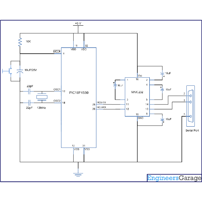
Circuit Diagrams
Project Components
Project Videot;
Filed Under: PIC Microcontroller.
t;
Filed Under: PIC Microcontroller.

Questions related to this article?
👉Ask and discuss on Electro-Tech-Online.com and EDAboard.com forums.
Tell Us What You Think!!
You must be logged in to post a comment.