Motion tracking sensors are used in applications like robotics, gesture recognition, vehicle stabilization, position control in drones/quadcopters, pointing devices, game controllers, and fitness tracking devices. One of the popular motion tracking sensors is MPU6050. It is a six-axis MEMS motion tracking sensor that includes a MEMS accelerometer and a MEMS gyroscope. The sensor also has a built-in temperature sensor where the temperature measurement can be used to calibrate the accelerometer and gyroscope. Plus, MPU6050 can be interfaced with an external magnetometer using an onboard I2C channel that extends the sensor to 9 DOF (Degree of Freedom). With an external magnetometer attached to MPU6050, a controller or computer can precisely track the exact movement.

Example of MPU6050 Motion Detection Sensor
The MPU6050 breakout board has a 3.3V voltage regulator that allows easy interfacing with 5V and 3.3V computers. Therefore, we can easily interface MPU6050 with Arduino, Raspberry Pi, ESP32, and several other microcontrollers and SBC platforms. In this project, we interfaced the MPU6050 motion tracker with Arduino and displayed its accelerometer, gyro, and temperature readings onto an SSD1306 OLED display.
Components required
- Arduino UNO x1
- MPU6050 sensor x1
- SSD1306 OLED module x1
- Connecting wires/Jumper wires
Software required
- Arduino IDE
How MEMS accelerometer works
Accelerometers are used for the detection of linear acceleration. These sensors can detect linear acceleration in one, two, or three dimensions. An accelerometer has a proof mass suspended by springs within a reference frame. The proof mass in a one-dimensional accelerometer has one degree of freedom. Similarly, proof-mass in a two-dimensional and three-dimensional accelerometer has 2 DOF and 3 DOF within the reference frame, respectively. The proof-mass acts like a suspended ball free to move within a cubical frame. When the sensor moves along a given axis, the suspended proof-mass experience a force in the opposite direction.
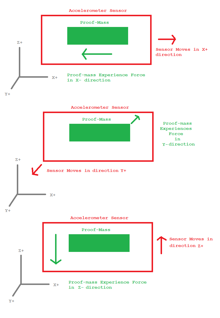
Working principle of accelerometer
If the acceleration sensed by the proof-mass is equivalent to gravitational acceleration, i.e., 9.8 m/s, it is said to be 1g. If a three-dimensional accelerometer senses a force of 1g in Z- direction, It is sensing the gravitational acceleration.
MEMS accelerometer consists of a micro-machined structure built on a silicon wafer. A proof-mass is suspended by polysilicon springs where it is free to deflect in one, two, or three dimensions on experiencing an external force. The proof-mass deflects between fixed plates which act as electrodes of a capacitor. On deflection along an axis, the distance between proof-mass and fixed plates is changed in proportion to the acceleration along that axis. This produces a proportional change in the capacitance of the fixed plates. The difference in capacitance is detected by a high-precision sensor which outputs a proportional analog voltage.
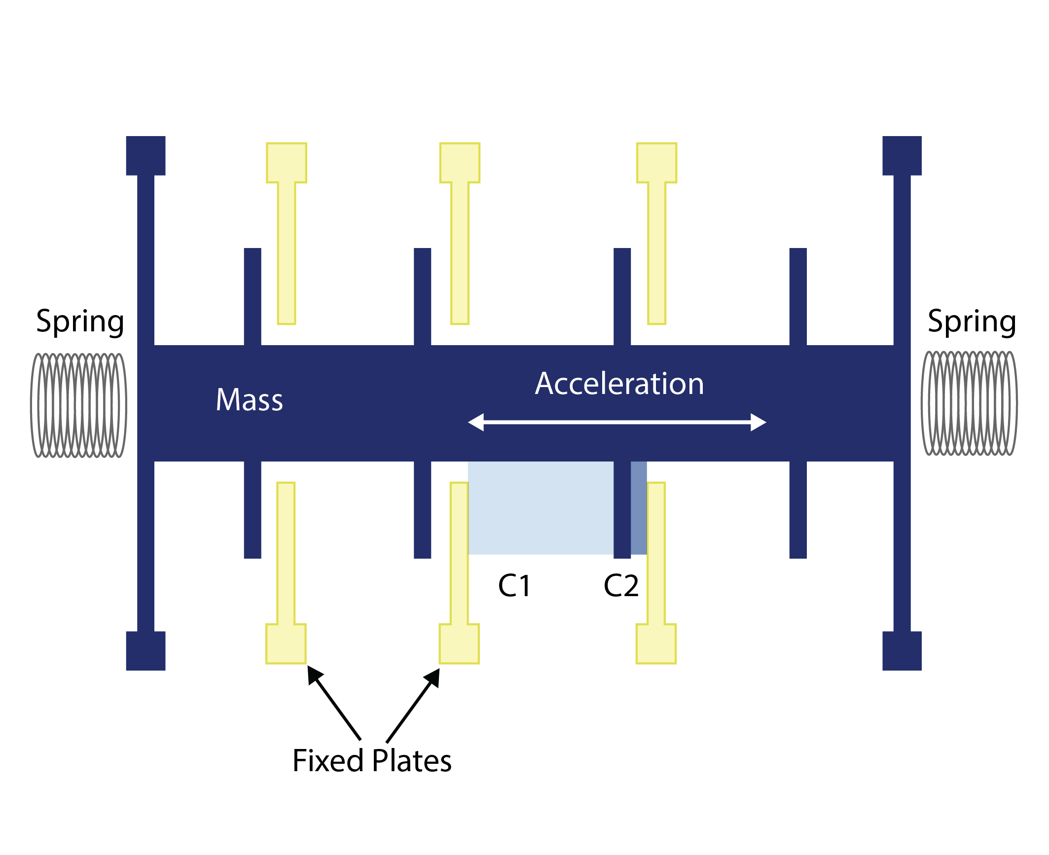
Structure of MEMS Accelerometer
How MEMS gyroscope works
A gyroscope is used to detect angular rotation. It uses the phenomenon called Coriolis Effect. Coriolis force is an inertial force experienced by an object moving in a rotating system perpendicular to the direction of motion and the axis of rotation.
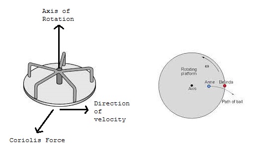
Example of Coriolis Effect
A Gyroscope consists of two proof-mass such that they are in an oscillating motion in opposite directions. When an angular force is applied to them due to rotation of the inertial frame, the Coriolis forces act upon the two masses in opposite directions. This causes a deflection of masses in opposite directions along the axis of Coriolis Force, causing a change in capacitance between them.
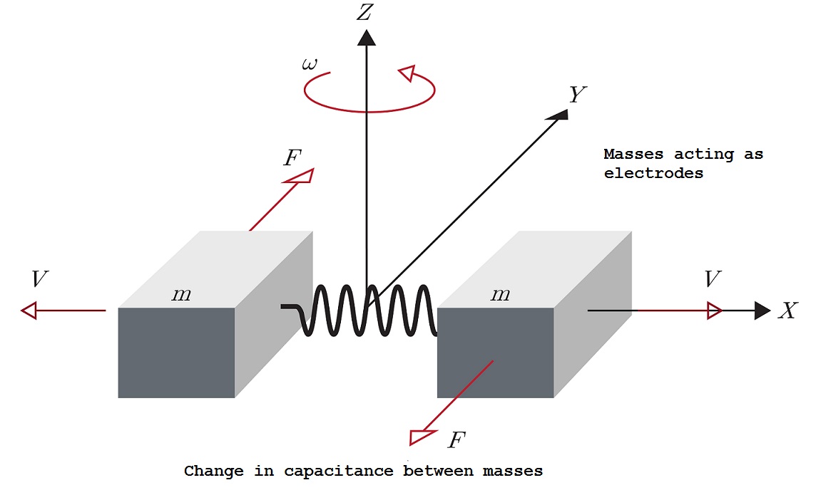
Working principle of MEMS gyroscope
MEMS gyroscope consists of a proof-mass which is divided into four parts. A fixed mass suspends each part in the center. The masses are continuously oscillating in and out along the horizontal plane.
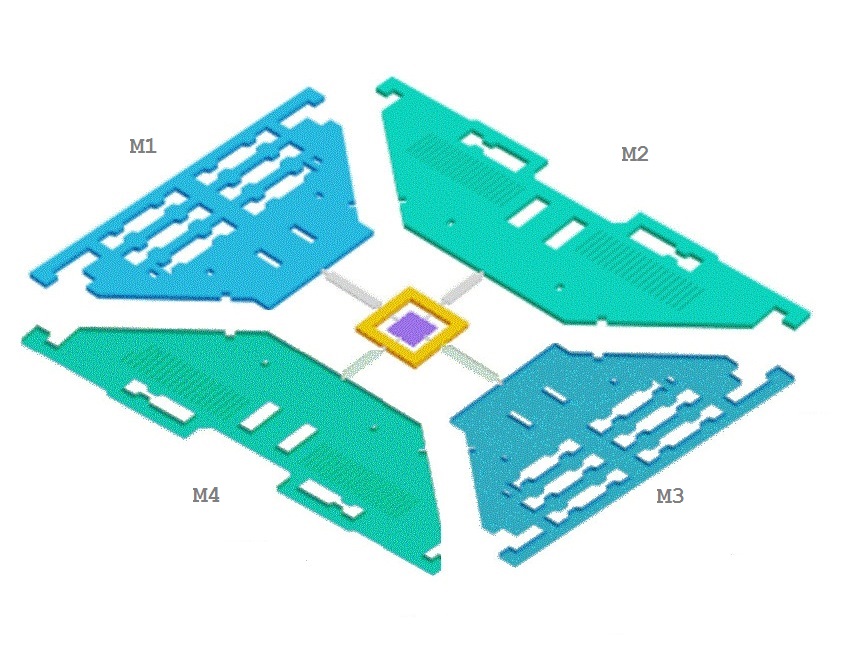
Structure of MEMS gyroscope
When the gyroscope rotates, the proof-masses going through a horizontal oscillating force experience a vertical force due to Coriolis Effect. There are three modes based on the axis of rotation.
When the axis of rotation is X-axis, the plates M1 and M3 move up and down, deflecting from the horizontal plane. This is called Roll Mode.
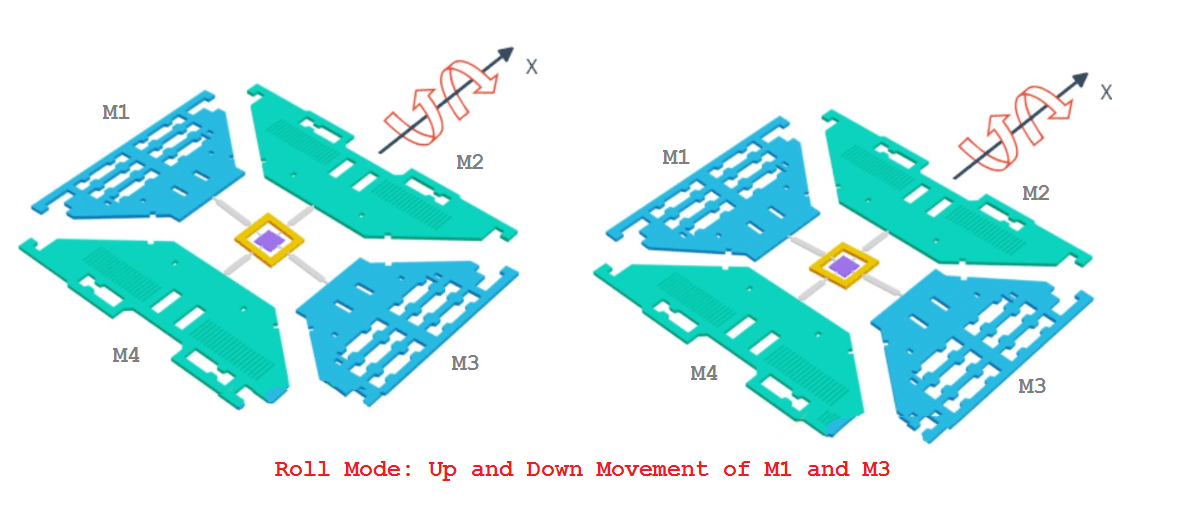
Roll mode in MEMS gyroscope
When the axis of rotation is Y-axis, the plates M2 and M4 move up and down, deflecting from the horizontal plane. This is called Pitch Mode.

Pitch mode in MEMS gyroscope
When the axis of rotation is Y-axis, plates M1 and M3 move in the opposite direction in the horizontal plane, and at the same time plates, M2 and M4 also move in the opposite direction in the horizontal plane. This is called Yaw Mode.
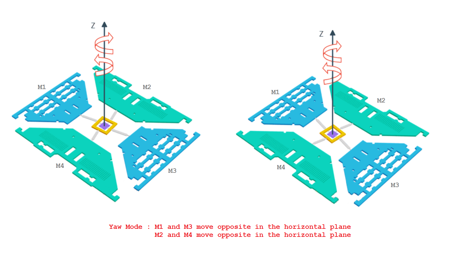
Yaw mode in MEMS gyroscope
When deflection in the driving masses causes a change in capacitance detected by a high precision sensor and converts to a proportional voltage signal.
MPU6050 motion tracking sensor
MPU6050 is a low-cost 6 DoF motion tracking sensor with a 3-axis on-chip accelerometer and a 3-axis on-chip gyroscope. It also includes a temperature sensor that measures the operating temperature of the silicon die in the range from -40˚C to 85˚C. It should be noted that the embedded temperature sensor in MPU6050 does not read the ambient temperature; it reads the operating temperature of the IC. The temperature measurements are used for the calibration of the accelerometer and gyroscope. The temperature measurement can also be used to detect temperature changes. MPU6050 has the following pin diagram
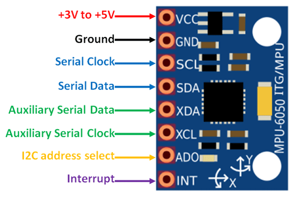
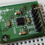
Pinout of MPU6050 Accelerometer Plus Gyro
MPU6050 finds its importance due to its on-chip Digital Motion Processor (DMP). The sensor’s DMP does all the complex calculations outputting direct acceleration and rotation values to any external controller/computer via an I2C interface. The sensor has two on-chip 16-bit analog-to-digital converters. One 16-bit ADC simultaneously converts the linear acceleration values in three axes detected by the on-chip accelerometer, which can be adjusted to four programmable scales – +/-2g, +/-4g, +/-8g, and +/-16g. Another 16-bit ADC simultaneously converts angular acceleration values in three axes of rotation (roll mode, pitch mode, and yaw mode) detected by the on-chip gyroscope. The gyroscope can be adjusted to four programmable scales of +/-250˚/s, +/-500˚/s, +/-1000˚/s, and +/-2000˚/s.
MPU6050 communicates with a controller/computer on the I2C interface. It has two I2C addresses – 0x68 and 0x69 to avoid any conflict with other I2C devices sharing the same bus. The I2C address of MPU6050 can be controlled from the ADO pin. If the ADO pin is not connected, the module has a default I2C address of 0x68. If the ADO pin is connected to 3.3V, the module has an I2C address of 0x69.
It is possible to connect an external magnetometer to MPU6050. The breakout board has a separate I2C bus on pins XDA and XCL. The breakout board also has an interrupt pin to raise a hardware interrupt on motion detection, shock, or fall.
Interfacing MPU6050 with Arduino
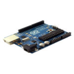
It is straightforward to interface MPU6050 with Arduino. The MPU6050 breakout board has an LD3985 3.3V regulator. So, we can directly interface the module with any 5V Arduino. The sensor can be powered from the Arduino’s supply, and the I2C pins of the module should be connected to the I2C port of Arduino. The I2C ports on Arduino UNO are shown in the image below.
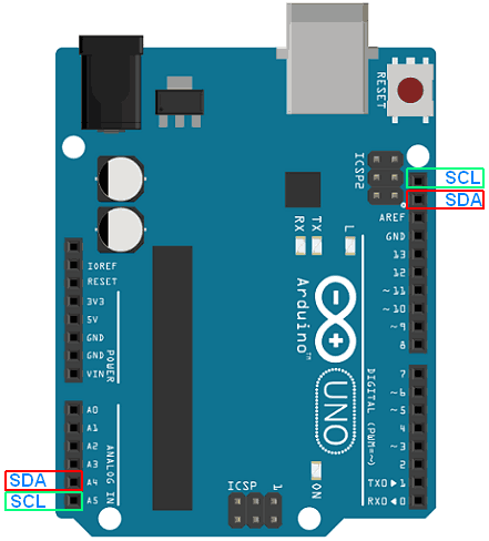
I2C ports on Arduino UNO
The interrupt pin of the MPU6050 can be connected to any GPIO of the Arduino.
Circuit connections
This project has an interface MPU6050 with Arduino UNO and displays the temperature, accelerometer, and gyroscope readings onto an SSD1306 OLED display. For interfacing MPU6050, the VCC and GND pins of MPU6050 are connected to 5V out, and ground pins of the Arduino; the SDA and SCL pins of the module are connected to the I2C port on Arduino, and the interrupt pin of the module is connected to pin D2 of the Arduino.
The SSD1306 is interfaced with Arduino using the physical SPI port of Arduino. For interfacing SSD1306 OLED via physical SPI port, connect the D0/SCK and D1/MOSI pins of SSD1306 OLED to pins D13 and D11 of Arduino, respectively. Connect pins DC, RESET, and CS of SSD1306 to pins D9, D10, and D8 of Arduino, respectively.
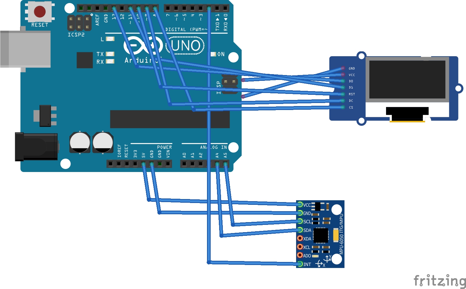
Circuit diagram of interfacing MPU6050 with Arduino
Arduino libraries for MPU6050
There are several Arduino libraries available for working with MPU6050. The Adafruit MPU6050 library from Adafruit is quite popular. We use the Arduino-MPU6050 library contributed by jarzebski from Github in this project. The library is licensed under GPL 3.0.
Arduino sketch
Programming guide
The sketch begins with importing Wire and Arduino-MPU6050 libraries for I2C communication with the MPU6050 sensor. The libraries for working with SSD1306 OLED are next imported. A constant ‘period’ is defined to store the time interval for reading values from the embedded temperature sensor, accelerometer, and gyroscope one by one. The constants for screen resolution and pin assignment of OLED display are declared. The objects of class Adafruit_SSD1306 and MPU6050 are instantiated. Next, a bitmap and array are defined to store the site logo.
In the setup() function, the baud rate for serial communication with Serial Monitor is set to 9600 bps. The MPU6050 sensor is tested using mpu.begin() method and is calibrated by calling mpu.calibrateGyro() method. The sensor scale is set by calling mpu.setThreshold() method. The OLED screen is initialized, and the site logo is flashed on it.
In the loop() function, the readings from the embedded temperature sensor, accelerometer, and gyroscope are sampled with a delay of 1 second and displayed on the OLED screen. The temperature is fetched by calling mpu.readTemperature() method. The gyroscope readings are fetched by calling mpu.readRawGyro() and mpu.readNormalizeGyro() methods. The normalized values for roll, pitch, and yaw modes are retrieved by calling normGyro.XAxis, normGyro.YAxis, and normGyro.ZAxis properties, respectively. Acceleration values are fetched by calling mpu.readRawAccel() and mpu.readNormalizeAccel() methods. The normalized acceleration values in X-, Y- and Z-axis are retrieved by calling normAccel.XAxis, normAccel.YAxis, and normAccel.ZAxis properties, respectively.
Results
You may also like:

Filed Under: Arduino, Electronic Projects, Sensors, Tutorials, Video

Questions related to this article?
👉Ask and discuss on EDAboard.com and Electro-Tech-Online.com forums.
Tell Us What You Think!!
You must be logged in to post a comment.