The Raspberry pi is a device which uses the Broadcom controller chip which is a SoC (System on Chip). This SoC has the powerful ARM11 processor which runs on 700 MHz at its core. This powerful processor and the controller having the peripherals like timers, interrupt controller, GPIO, PCM / I2S, DMA controller, I2C, SPI slave, PWM, UART, USB, graphical processing unit (GPU) which includes VideoCore, MPEG-2 and MPEG-4 and a 512 MB SDRAM makes it a mini-computer.
The Raspberrypi board is powerful enough to run large operating systems like Linux, Mac and Windows. Linux operating systems especially Ubuntu is preferred for all kind of programming and development. The operating systems like Archlinux ARM, OpenELEC, Pidora, Raspbmc, RISC OS and the Raspbian and also Ubuntu versions are available for the Raspberrypi board. The immediate advantage of having an Operating System like Ubuntu running on an embedded system device like Raspberrypi is Multi-User-Multitasking.
A Multitasking Operating System can control the processes running on it by sending signals to them. A user can sometimes initiate a signal sending and the processes can also send signals to each other. A process can request the OS to send a signal called SIGALARM to it after a specified time and such a signal is useful in several situations. This project discusses about the coding that has to be done to receive the SIGALRM signal continuously with a specified time interval between each signals. This mechanism serves just like using the timer modules in the microcontrollers.
In this project the Raspberrypi board is loaded with Ubuntu and is remotely accessed using VNC. The Raspberrypi board is also connected to the internet. There are 26 connectors which can be taken out from the connector port of the Raspberrypi board. All the connector pins are taken out using 13*2 pin female connectors and at the other end of their wire 26 pin Burg stick male connectors are attached. The Burg stick male connectors allow each pin out from the Raspberrypi board to be plugged into the holes of a breadboard. To access the pins that coming out of the Broadcom controller of the Raspberrypi board using C language, a C library is available called “bcm2835” which has been downloaded and installed.
A signal is sent for the purpose of notifying the process about something that required immediate attention. Different signals are used to notify different events and the signals are differentiated by their signal numbers. The list of all the available signals in the OS and their signal numbers can be obtained using the following command;
kill -l
The following table gives a list of the most common signals that a process might encounter in an Operating System;
|
NAME |
NUMBER |
DESCRIPTION |
|
SIGHUP |
1 |
Linux sends a process this signal when it becomes disconnected from a terminal. |
|
SIGINT |
2 |
Linux sends a process this signal when the user tries to end it by pressing CTRL+C. |
|
SIGILL |
4 |
Linux sends a process this signal when it attempts to execute an illegal instruction. |
|
SIGABRT |
6 |
Linux sends a process this signal to the process when the process calls the ‘abort ()’ function |
|
SIGFPE |
8 |
Linux sends a process this signal when it has executed an invalid floating-point math instruction |
|
SIGKILL |
9 |
Linux sends a process this signal to end it immediately |
|
SIGUSR1 |
10 |
User programs can send this signal to other process |
|
SIGUSR2 |
12 |
User programs can send this signal to other process |
|
SIGSEGV |
11 |
Linux sends a process this signal when the program has attempted an invalid memory access |
|
SIGPIPE |
13 |
Linux sends a process this signal when the program has attempted to access a broken data stream, such as a socket connection that has been already closed |
|
SIGALRM |
14 |
A process can receive this signal from the Linux using the function alarm(), after a time period mentioned in its argument. |
|
SIGTERM |
15 |
Linux sends a process this signal requesting it to terminate |
|
SIGCHLD |
17 |
Linux sends a process this signal when a child process exits |
|
SIGXCPU |
24 |
Linux sends a process this signal when it exceeds the limit of CPU time that it can consume. |
|
SIGVTALRM |
26 |
A process can receive this signal from the Linux using the function setitimer (), after a time period mentioned in its argument. |
Fig. 2: List of common signals for using Timer process in Operating System
This particular project is based on continuously receiving and handling the signal number 14, the SIGALRM. A process can receive the SIGALRM signal from the OS by calling a function named ‘alarm ()’, the prototype of which is defined in the header file <signal.h>.
The OS will send the SIGALRM to the process after a time period mentioned in the parameter passed to the function during the function call. A single call to the alarm () will receive a single SIGALRM signal only. To receive a SIGALRM at continuous interval of time, the same function needs to be called after receiving each SIGALRM. The better method is to use set a timer which can continuously generate the SIGALRM signals at specified intervals of time.
The ‘set interval timer’ function can be used to set a timer which can continuously generate the SIGALRM signals at specified intervals of time. The details of the function ‘setitimer ()’ which is used for this purpose is discussed below;
setitimer ()
Using this function a timer can be set which will down count from the specified value and generates an interrupt as it reaches zero and then resets to the previous value. The function ‘setitimer ()’ is defined in the header file <sys/time.h> as given below;
int setitimer (
int which,
const struct itimerval *new_value,
struct itimerval *old_value
);
The first argument asks for the type of the timer that needs to be enabled. The OS provides each process to enable timers in three different modes. The timer sends different signals when operating in each modes and the signal SIGALRM is send only when the timer is operating as Real Time timer. To enable the timer as Real Time timer, the function ‘setitimer ()’ should be called with the first parameter as ‘ITIMER_REAL’. The parameters ITIMER_VIRTUAL, or ITIMER_PROF can also be passed to the function to enable the timer as a virtual timer (which runs only when the process is in execution) or when it is required for the process profiling (to find out how much time the process spends in CPU) respectively.
The ‘setitimer ()’ function sets a new the timer specified by values inside the structure which is passed as the second parameter in the function call. The third parameter can be used to read the values of an already existing timer. Timer values are defined by the following structures:
struct itimerval
{
struct timeval it_interval; /* value of the required interval between signals */
struct timeval it_value; /* value of time period to generate the first signal */
};
struct timeval
{
time_t tv_sec; /* interval value when it is in seconds range */
suseconds_t tv_usec; /* interval value when it is in microseconds range */
};
The following statements show how to set up a timer for 2 seconds using the function setitimer ().
struct itimerval timer1;
timer1 . it_interval . tv_usec = 0;
timer1 . it_interval . tv_sec = 2;
timer1 . it_value . tv_usec = 0;
timer1 . it_value . tv_sec = 2;
setitimer ( ITIMER_REAL, &timer1, NULL );
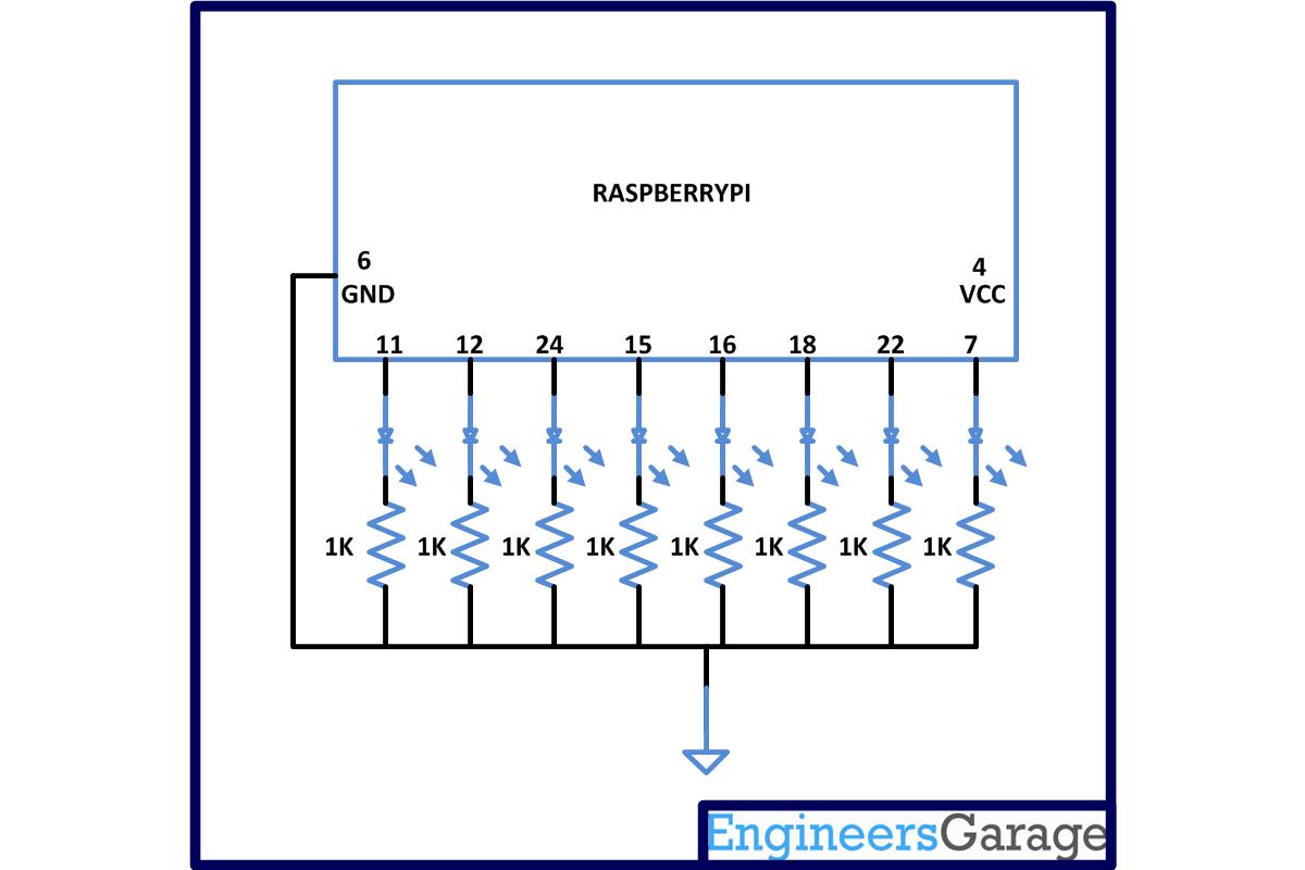
The setitimer () function is used in the coding done for this particular project which continuously toggles LEDs with a delay of 2 seconds.
***Note that in this project the latest version of library “bcm2835” is used with an old version of Raspberrypi board. It is not possible to access the pin number 13 of the old board with the latest library version and hence in the the pin number 24 is used to blink the 3rd LED. The circuit diagram is also drawn accordingly. Those who have the latest version of the board can use the pin 13 without any trouble.
To find the ‘Revision’ and other important details about the Raspberrypi board, use the following command;
cat /proc/cpuinfo
Project Source Code
###
#include <bcm2835.h>#include <pthread.h>#include <unistd.h>#include <signal.h>#include <sys/time.h>#define PIN1 RPI_GPIO_P1_11#define PIN2 RPI_GPIO_P1_12#define PIN3 RPI_GPIO_P1_24#define PIN4 RPI_GPIO_P1_15#define PIN5 RPI_GPIO_P1_16#define PIN6 RPI_GPIO_P1_18#define PIN7 RPI_GPIO_P1_22#define PIN8 RPI_GPIO_P1_07void sig_handler ( int signo );void set_pins_output ( void );void set_all_pin_low ( void );void timer_seconds ( long int seconds );void timer_useconds ( long int useconds );int main(){if (!bcm2835_init())return 1;set_pins_output ();set_all_pin_low ();signal ( SIGALRM, sig_handler );timer_seconds ( 2 );while ( 1 );bcm2835_close();return 0;}void timer_seconds ( long int seconds ){struct itimerval timer1;timer1 . it_interval . tv_usec = 0;timer1 . it_interval . tv_sec = seconds;timer1 . it_value . tv_usec = 0;timer1 . it_value . tv_sec = seconds;setitimer ( ITIMER_REAL, &timer1, NULL );}void timer_useconds ( long int useconds ){struct itimerval timer2;timer2 . it_interval . tv_usec = useconds;timer2 . it_interval . tv_sec = 0;timer2 . it_value . tv_usec = useconds;timer2 . it_value . tv_sec = 0;setitimer ( ITIMER_REAL, &timer2, NULL );}void set_all_pin_low ( void ){bcm2835_gpio_write(PIN1, LOW);bcm2835_gpio_write(PIN2, LOW);bcm2835_gpio_write(PIN3, LOW);bcm2835_gpio_write(PIN4, LOW);bcm2835_gpio_write(PIN5, LOW);bcm2835_gpio_write(PIN6, LOW);bcm2835_gpio_write(PIN7, LOW);bcm2835_gpio_write(PIN8, LOW);}void set_pins_output ( void ){bcm2835_gpio_fsel(PIN1, BCM2835_GPIO_FSEL_OUTP);bcm2835_gpio_fsel(PIN2, BCM2835_GPIO_FSEL_OUTP);bcm2835_gpio_fsel(PIN3, BCM2835_GPIO_FSEL_OUTP);bcm2835_gpio_fsel(PIN4, BCM2835_GPIO_FSEL_OUTP);bcm2835_gpio_fsel(PIN5, BCM2835_GPIO_FSEL_OUTP);bcm2835_gpio_fsel(PIN6, BCM2835_GPIO_FSEL_OUTP);bcm2835_gpio_fsel(PIN7, BCM2835_GPIO_FSEL_OUTP);bcm2835_gpio_fsel(PIN8, BCM2835_GPIO_FSEL_OUTP);}void sig_handler ( int signo ){static int i = 0;set_all_pin_low ();bcm2835_delay( 50 );i ++;switch ( i ){case 1:bcm2835_gpio_write(PIN1, HIGH);break;case 2:bcm2835_gpio_write(PIN2, HIGH);break;case 3:bcm2835_gpio_write(PIN3, HIGH);break;case 4:bcm2835_gpio_write(PIN4, HIGH);break;case 5:bcm2835_gpio_write(PIN5, HIGH);break;case 6:bcm2835_gpio_write(PIN6, HIGH);break;case 7:bcm2835_gpio_write(PIN7, HIGH);break;case 8:bcm2835_gpio_write(PIN8, HIGH);i = 0;break;};}###
Circuit Diagrams
Project Components
Project Video
Filed Under: Raspberry pi
Filed Under: Raspberry pi

Questions related to this article?
👉Ask and discuss on Electro-Tech-Online.com and EDAboard.com forums.
Tell Us What You Think!!
You must be logged in to post a comment.