Interrupts are special events that require immediate attention. They cause the processor to cease the running task to serve a special task for which the interrupt event had occurred. After the special task is over, the processor resumes performing the original task.
A PIC microcontroller consists of both software and hardware generated interrupts. The hardware interrupts are produced by external hardware at certain pins of the microcontroller. The software interrupts, on the other hand, are generated by internal peripherals of the controller. This software interrupt helps the programmer to use more than one internal peripheral in single application and serve them individually when they respond.
· Reset, Brown-Out Reset, Watch-dog Reset, Power On Reset
· External Interrupt 0 (INT0)
· External Interrupt 1 (INT1)
· External Interrupt 2 (INT2)
· Timer 0 Interrupt
· Timer 1 Interrupt
· Timer 2 Interrupt
· Timer 3 Interrupt
· ADC Interrupt
· Analog Comparator Interrupt
· RB Port change Enable Interrupt
· Streaming Parallel Port Read/Write Interrupt
· EUSART Receive Interrupt
· EUSART Transmit Interrupt
· Master Synchronous Serial Port Interrupt
· CCP1 Interrupt (Capture, Compare, PWM)
· Oscillator Fail Interrupt
· USB Interrupt
· Data EEPROM/Flash Write Operation Interrupt
· Bus Collision Interrupt
· High/Low-Voltage Detect Interrupt
· CCP2 Interrupt
|
Bit 7
|
Bit 6
|
Bit 5
|
Bit 4
|
Bit 3
|
Bit 2
|
Bit 1
|
Bit 0
|
|
GIE/GIEH
|
PEIE/GIEL
|
TMR0IE
|
INT0IE
|
RBIE
|
TMR0IF
|
INT0IF
|
RBIF
|
Fig. 2: Bit Configuration of INTCON /Interrupt Control Register 1 for various hardware interrupt operation in PIC Microcontroller
|
Bit 7
|
Bit 6
|
Bit 5
|
Bit 4
|
Bit 3
|
Bit 2
|
Bit 1
|
Bit 0
|
|
RBPU
|
INTEDG0
|
INTEDG1
|
INTEDG2
|
—
|
TMR0IP
|
—
|
RBIP
|
|
Bit 7
|
Bit 6
|
Bit 5
|
Bit 4
|
Bit 3
|
Bit 2
|
Bit 1
|
Bit 0
|
|
INT2IP
|
INT1IP
|
—
|
INT2IE
|
INT1IE
|
—
|
INT2IF
|
INT1IF
|
Project Source Code
###
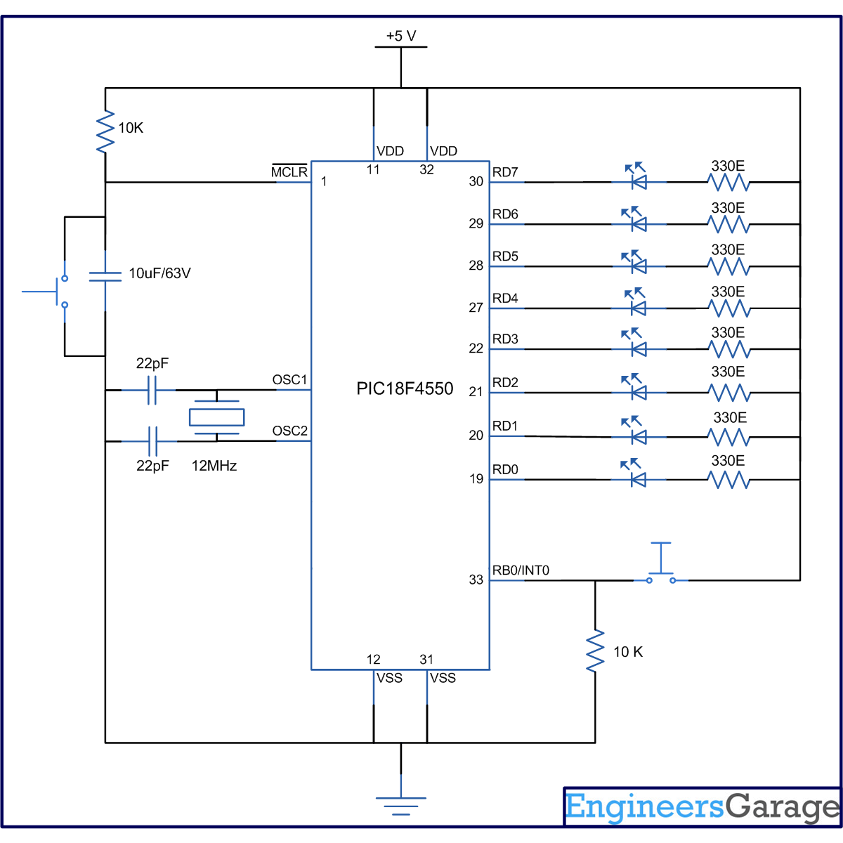
//Program to depict the working of External Interrupt0 of PIC18F4550 void main() { TRISD=0; // Configure PortD as output port INTCON=0x10; // Enable INT0 INTCON2=0; // Set Falling Edge Trigger for INT0 INTCON.GIE=1; // Enable The Global Interrupt while(1) { LATD=0x55; //Set some value at PortD } } void interrupt() // Interrupt ISR { INTCON.INT0IF=0; // Clear the interrupt 0 flag LATD=~LATD; // Invert (Toggle) the value at PortD Delay_ms(1000); // Delay for 1 sec }###
Circuit Diagrams
Project Components
Project Video
Filed Under: PIC Microcontroller.
Filed Under: PIC Microcontroller.

Questions related to this article?
👉Ask and discuss on Electro-Tech-Online.com and EDAboard.com forums.
Tell Us What You Think!!
You must be logged in to post a comment.