RF Modules are extensively used by the electronics hobbyists. They are also used in large number of consumer electronics products. These modules are used for wireless data transmission and for implementing remote control systems. The 434 MHz RF module is the most commonly used module available in the markets. These modules are capable of transmitting 4-bit data at once at a data rate of 1Kbps to 10 Kbps. Learn about the RF transmission and basic setup of the RF transmitter and receiver modules.
The typical operational range of 434 MHz RF modules is between 50 metre to 80 metre. The operational range of the RF module can be increased manifold by attaching external antennas to the RF transmitter and receiver. Learn about the sole effect of attaching antenna of standard size on the operational range of RF module.
The range of the RF module can be further increased by increasing the transmission power of the antennas. This project is a demonstration of increasing operational range of RF module by increasing the transmission power after the antennas of standard size as according to the antenna theory are already attached to the transmitter and receiver sections.
Components Required
| Sr. NO. | Name of the Component | Required Qty. |
|---|---|---|
| 1 | RF Tx Module (434 Mhz) | 1 |
| 2 | RF Rx Module (434 Mhz) | 1 |
| 3 | HT12E | 1 |
| 4 | HT12D | 1 |
| 5 | LED | 5 |
| 6 | Resistor – 1KΩ (Quarter watt) | 8 |
| 7 | Resistor – 1MΩ (Quarter watt) | 1 |
| 8 | Resistor – 50KΩ (Quarter watt) | 1 |
| 9 | Pushbutton | 4 |
| 10 | Battery – 9V | 4 |
| 11 | Bread Board | 2 |
| 12 | Connecting wires | – |
Fig. 1: Block Diagram of RF Transmitter and Receiver
Circuit Connections
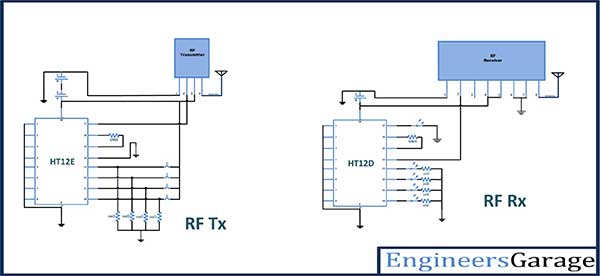
The circuit connections are made as specified by the datasheets of the RF module and the encoder and decoder ICs. The antennas of height 17.25 cm are connected to the receiver and transmitter sections in addition to the basic setup. Both the HT12E encoder and HT12D decoder IC are hardwired to have address of 0x00. The pin 14 of the encoder IC is grounded to allow uninterrupted transmission of signal. The push-to-on switches are used on the data pins of encoder IC to change the data bits in range from 0x1 to 0xF on every reading.
In the receiver section, LEDs are connected to the data pins of the decoder IC to get a visual hint of the change in transmitted and thereof received data bits. The LEDs are connected between the data pins and ground with 1K ohm pull-up resistors in series. This circuit configuration allows LEDs to glow on receiving a HIGH bit while switching off on receiving a LOW bit.
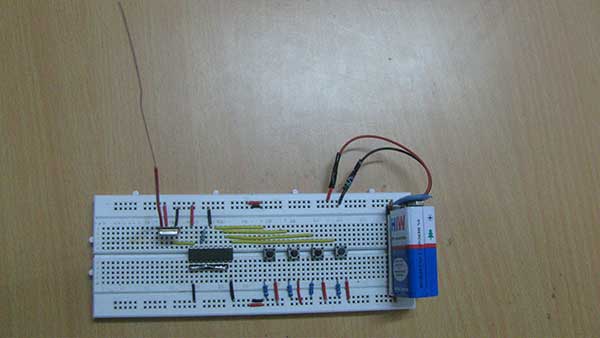
Fig. 2: Prototype of RF Transmitter
The antennas of height 17.25 cm are connected to pin 4 of the RF transmitter in transmitter section and pin 8 of RF receiver in the receiver section. The power supply to the circuits is provided by 9V batteries. In first and second phase of the experiment, single 9V batteries are used to power the circuits. In third phase of the experiment, two 9V batteries are connected in parallel to supply power to both the circuits. In fourth and final phase of the experiment, two 9V batteries are connected in series to supply power to both the circuits.
The antennas are simple wires cut to lengths of 17.25 cm which is the quarter of the wavelength of the carrier wave of 434MHz RF module.
How the circuit works
The experiment is carried out in four phases. First the range of RF module is tested without antenna. The module is taken to an open place where straight distance between the transmitter and receiver can be measured using a tape. The distance between the transmitter and receiver is kept 10 metre and data bit is changed to test the reception of signal at the receiver section. The distance is increased by 10 metre in each subsequent test and the test is stopped when no change in data bit is reflected on the receiver section after a certain distance. In the first phase when RF module is used without antenna, the operational range of RF module is found to be 68 metre.
In second phase, antennas of standard height i.e. 17.25 cm are connected to both transmitter and receiver sections and both sections are powered by single 9V batteries. The range of RF module is again tested by increasing the distance between transmitter and receiver in increments of 10 metre and later for precise reading in increments of 1 metre, then changing the data bit for testing in each step. In the second phase when external antennas are attached and power transmission is kept constant to be 9V, the extended operational range of RF module is found to be 150 metre.
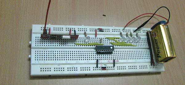
Fig. 3: Prototype of RF Receiver
In third phase, the power supply to the transmitter and receiver circuits is replaced with two 9V batteries connected in parallel to each section. On parallel connection of batteries, the current supplied to the circuit and the antennas is increased but the supply voltage is halved to 4.5V. Due to reduction in supply voltage, power transmission to the circuits and the antennas is reduced and the operational range of the RF module is also reduced. In third phase when parallel connected batteries supply power to the transmitter and receiver sections, the operational range of the module is found to be 100 metre.
In fourth phase, the transmitter and receiver sections are powered by two 9V batteries connected in series each. The series connection of batteries keeps the current supplied to the circuits and the antennas same but doubles the supply voltage to 18V. Due to increase in supply voltage, power transmission to the antennas is increased and the operational range of the RF module is also increased. In the fourth and final phase of the experiment when serially connected batteries power both the sections, the operational range of the RF module is found increased to 300 metre.
| a. | Constant Power Supply without Antenna (9V) | 68 m |
| b. | Constant Power Supply with Antenna ( 9V + Antenna ) | 150m |
| c. | Variable Power Supply without Antenna ( Two 9V Batteries in parallel ) | 100m |
| d. | Variable Power Supply with Antenna ( Two 9V Batteries in parallel + Antenna ) | 300m |
The experiment shows that the power transmission to the antennas can be increased by increasing the supply voltage. The operational range of the RF module is directly proportional to power transmission. It can be doubled by doubling the supply voltage.
You may also like:
Circuit Diagrams
Filed Under: Tutorials






Questions related to this article?
👉Ask and discuss on EDAboard.com and Electro-Tech-Online.com forums.
Tell Us What You Think!!
You must be logged in to post a comment.