The inductance meter is a device that can be used to measure the unknown inductance of an inductor or a simple coil. This project discusses the concept and the technique of measuring the inductance with a microcontroller board. This project makes use of the resonance frequency of a tank circuit, in which there will be a capacitor and an unknown inductance connected in parallel. The natural resonating frequency of the tank circuit varies with the value of the inductor connected. The frequency is measured and the value of inductance is calculated with the help of simple mathematical equations.

Fig. 1: Prototype of Arduino based Inductance Meter
The Arduino board is used to develop this simple prototype of inductance meter, so reader needs to know how to start with arduino.The arduino board has all the required circuitry to get the built-in AVR microcontroller running. The AVR microcontroller boards which are provided with all the basic circuitry for the operation of the microcontroller which has been flashed with the Arduino boot-loader are called Arduino boards. The Arduino IDE is so simple to use that anyone who has basic knowledge of c programming can quickly get started with it. The output of the device can be viewed in the Serial monitor window of the Arduino IDE or in any Serial port accessing software like Hyperterminal, Putty, Mtty etc.
Description
It is assumed that the reader has gone through the project how to get started with the arduino and done all the things discussed in it.
The Arduino based inductance meter explained in this project is basically a frequency meter which measures the resonating frequency of a tank circuit. The tank circuit is a general term representing an inductor and a capacitor connected in parallel. This circuit is also called parallel LC circuit, in which the ‘L’ denotes the inductance and the ‘C’ denotes the capacitor.

Fig. 2: Image showing LC Circuit
This tank circuit is made to oscillate at its resonating frequency by suddenly discharging it after a period of constant charging. Once started discharging the tank circuit will oscillate at its resonating frequency, or simply it will resonate while discharging. The amplitude of the oscillation keeps on decreasing each time it oscillates and finally the oscillation dies out at the point of time when the tank circuit is completely discharged. This type of oscillation is called ‘Damped oscillation’

Fig. 3: Overview of Arduino based Inductance Meter
The above image is the representation of a damped oscillation happening at the output of a LC tank circuit. The frequency of the oscillation is related to the value of the inductor ‘L’ and the capacitor ‘C’ in the circuit and is given by the following equation.

Fig. 4: Image showing Formula of Frequency for LC Circuit
Working
The Damped oscillation can also be observed on a CRO when a square wave of high frequency is applied to a tank circuit as shown in the following image.

Fig. 5: Image showing waveforms of damped oscillations on CRO
The Arduino board in this project charges a tank circuit, in which the value of inductance need to be found out is connected in parallel with a capacitor. The Arduino board suddenly discharges it at a point of time and let is resonate. The frequency at which the circuit resonates will be measures and from that the inductance is measured.

Fig. 6: Image of Damped Oscillations
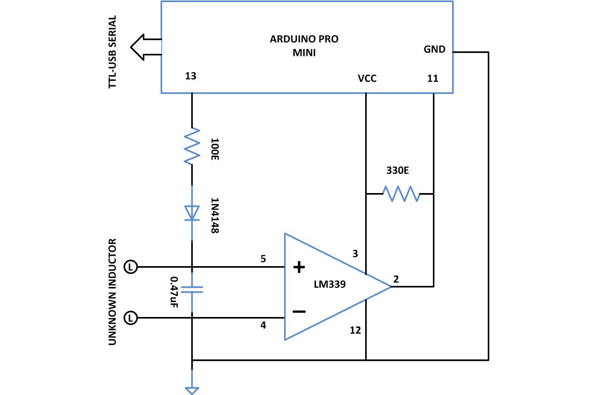
Since the oscillation of a LC tank circuit will always be in the form of a sine wave and the Arduino is a digital device, there need some circuitry which helps in reading the frequency of the Damped oscillation of the LC circuit. This is achieved with the help of a ‘Zero crossing detector’ made with a comparator IC, LM339. The output of the Zero crossing detector becomes high when the sine wave starts the positive half cycle and will remain high till the time sine wave starts the negative half cycle. Thus for one cycle of a sine wave the output of the Zero crossing detector will generate a square wave which is having a time period exactly half of that of the sine wave.

Fig. 7: Image showing ouutput waveforms of LC Circuit and LM339
The time period of all the square waves will be same since for the Damped oscillation, only the amplitude keeps on decreasing with each cycle but the frequency remains the same. The Arduino board measures the time period of the first square wave after the tank circuit is discharged and takes the time period ‘T’ of the oscillation as double that value. The frequency of the oscillation is then calculated by taking the inverse of that value.
F = 1/2T
The value of the unknown inductance ‘L’ is then calculated from the known values of capacitance ‘C’ connected in the circuit, and the frequency ‘F’ of the damped oscillation of the tank circuit.
L = 1/4?2F2C
Calculating the frequency by measuring the time period of square wave is very easy using the Arduino code, the built-in function ‘pulseIn()’ helps to do that. The function returns the time period of a pulse which appears at the specified pin, as an example the statement,
pulse = pulseIn(11,HIGH,5000);
returns the value of the time period in which a pulse remained high at the pin 11. The third parameter is optional for this function which sets a time out till a pulse appears on the specified pin.
Note:
This prototype can measure only very high inductance values. The value may vary slightly with each reading due to the tolerance of the capacitor. The users are suggested to add some calibration value with the actual value if it is required.

Fig. 8: Image showing inductance measurement on serial port of Arduino IDE
Project Source Code
###


double pulse,frequency,capacitance,inductance;


void setup()
{
    Serial.begin(115200);
    pinMode(11,INPUT);
    pinMode(13,OUTPUT);
    Serial.println("============ INDUCTANCE METER ============");
    delay(1000);
}
void loop()
{
  digitalWrite(13,HIGH);
  delayMicroseconds(5000);
  digitalWrite(13,LOW);
  delayMicroseconds(100);
  pulse=pulseIn(11,HIGH,5000);
   if(pulse>0.1)
   {
      capacitance=47.E-8;//Currently using 0.47uF
      frequency=1.E6/(2*pulse);
      inductance=1./(capacitance*frequency*frequency*4.*3.14159*3.14159);
      inductance*=1E6;
      Serial.print("tinductance uH:");
      Serial.println(inductance);
      delay(500);
   }
}

###
Circuit Diagrams
Project Video
Filed Under: Electronic Projects
Filed Under: Electronic Projects

Questions related to this article?
👉Ask and discuss on EDAboard.com and Electro-Tech-Online.com forums.
Tell Us What You Think!!
You must be logged in to post a comment.