Here given project is the real control panel for any unipolar stepper motor which is designed to run motor at lower RPM (as much as upto 10 RPM) to take greater load and provide extra heavy torque. This project is for specialize stepper motor which has technical specifications like
Voltage ratings: – from 5 to 30 V DC or more then that
Torque:- 1.5 Kg/cm minimum.
Current :- 500 mA to 2 Amp
RPM: – 30 rpm max.
Step angle:- 1.8 deg/pulse (200 pulses for 1 revolutions)
The motor is used in textile industries or in CNC machines for various operations/applications like viving bobbin of string, cutting axes of diamond etc.
This is a complete industrial stepper motor driver in which the program gradually increases the stepper motor speed to its maximum level when you start it. One can easily change the speed of motor in between the operation also he can change direction (from clockwise to anticlockwise).
The program starts the motor from minimum speed that is 10 RPM and gradually increase it to its maximum value in step of 5 (10, 15, 20… likewise).
The most interesting part is one can also program the motor to automatically reverse after predetermined time (set by user). Means for some time it will rotate in clockwise direction and automatically after some time it will change the direction and start rotating anticlockwise again after some time (entered by user) it will change direction.
Again the program is divided in to two parts. One is hardware part second is software part.
Hardware part includes switching circuit and driver circuit which actually rotates the motor. Software part is controlling part which controls all the parameters of motor. Lets starts with hardware part first.
Hardware part: –
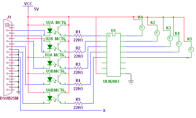
Complete circuit is quite big so it is divided in two sections. One section includes opto-couplers (datasheet), ULN2003A (datasheet) chip and relays. Second section includes multivibrator, and stepper motor driver. Figure given in Circuit Diagram Tab1 shows first section of circuit.
Connections: – As shown in figure five opto-couplers are used to drive relays through ULN chip using LPT port of PC. The anodes and collectors of every opto-couplers are tied with Vcc. The cathode of each opto-coupler is connected with data pins D0(2) – D4(6). Emitters of each opto-coupler are connected to inputs of ULN chip through current limiting resistors. Outputs of ULN drive relay coils.
Second section of circuit is as shown in Circuit Diagram tab2. It includes IC555(datasheet) as astable multivibrator, decade counter chip 4017(datasheet), and ULN2003A. Output frequency of IC555 can be changed by changing the resistor R2 to R6. This output is given as clock input to counter IC. Its four outputs are given as input to ULN chip. Q0 and Q2 outputs are given directly while Q2 & Q4 outputs are given through 2 C/O relay as shown. Outputs of ULN chip is connected with stepper motor coil.
Hardware Operation
Operation: –
- Sending low logic on any data pin of LPT will turn on that opto-coupler.
- It will send high op to input of ULN chip. That will switch on the relay.
- When relay is switched on one of the resistor from R2 – R6 get connected to IC555 and it will start generating pulses.
- Depending upon the resistor connected the op pulse frequency will be
|
Sr. No. |
Transistor |
Resistor |
Frequency |
RPM |
|
1 |
Q1 |
R2 = 6.8 K |
100 Hz |
30 |
|
2 |
Q2 |
R3 = 9.1 K |
75 Hz |
25 |
|
3 |
Q3 |
R4 = 10 K |
70 Hz |
20 |
|
4 |
Q4 |
R5 = 15 K |
50 Hz |
15 |
|
5 |
Q5 |
R6 = 20 K |
35 Hz |
10 |
- Above table also shows the RPM of motor when one particular resistor is connected.
- When 4017 receives this pulse input it will produce the output on Q0 – Q3 (1, 2, 3, 4) in this manner
|
Outputs |
|||
|
1 |
2 |
3 |
4 |
|
1 |
0 |
0 |
0 |
|
0 |
1 |
0 |
0 |
|
0 |
0 |
1 |
0 |
|
0 |
0 |
0 |
1 |
- This sequence will rotate motor in one direction. To change the direction switch on 2 C/O relay. It will change the sequence
|
Outputs |
|||
|
1 |
2 |
3 |
4 |
|
1 |
0 |
0 |
0 |
|
0 |
0 |
0 |
1 |
|
0 |
0 |
1 |
0 |
|
0 |
1 |
0 |
0 |
- So motor will start rotating in another direction.
- Thus by switching relays K1 – K5 will change the RPM of motor and by switching 2 C/O relay will change the direction.
Software Section
Software Section:-
The figure given below shows application design.
There are total 6 buttons, 2 radio buttons, 3 group boxes, 3 static texts and 1 edit box. To set their properties please refer the table.
|
Sr. No. |
Item |
Property |
Setting |
|
1 |
Button |
ID Caption |
IDC_STRT Start Rotating |
|
2 |
Button |
ID Caption |
IDC_STP Start Rotating |
|
3 |
Button |
ID Caption |
IDC_INC Increase |
|
4 |
Button |
ID Caption |
IDC_DEC Decrease |
|
5 |
Button |
ID Caption |
IDC_STR Start |
|
6 |
Button |
ID Caption |
IDC_STOP Stop |
|
7 |
Radio Button |
ID Caption |
IDC_CLK Clockwise |
|
8 |
Radio Button |
ID Caption |
IDC_ACLK Anticlockwise |
|
8 |
Group Box |
caption |
Direction |
|
9 |
Group Box |
caption |
Speed |
|
10 |
Group Box |
caption |
Automatic reversible mode |
|
11 |
Static Text |
caption |
RPM |
|
12 |
Static Text |
caption |
Enter time in sec. :- |
|
13 |
static Text |
ID caption |
IDC_CNT 0 |
|
14 |
Edit Box |
ID |
IDC_TIME |
After completing the design now we have to attach two variables with IDC_CNT and IDC_TIME. So open class wizard and open member variables. Click on particular ID and attach variables m_scnt of type CSring with IDC_CNT and m_itime of type int with IDC_TIME. Attach one more variable to dialog class of int type with name m_c.
Now for timer event we need to add one more ID to handle timer functions. For this open resource view and right click on resources and select resources symbols from popup menu. Click new and give IDC_CLK_TMR as name and 1 as value.
Now we have to attach function with each button as well as radio button. For this just double click on each button and leave the name of the function as it is just click OK. Then open class wizard select dialog ID and then select WM_TIMER event. Click on add function button.
Project Source Code
Project Source Code
###
void CStepDlg::OnInc()
{
// TODO: Add your control notification handler code here
UpdateData(TRUE);
x++;
if(t==0)
{
switch(x)
{
case 1:
_outp(0x0378,0x10);
break;
case 2:
_outp(0x0378,0x08);
break;
case 3:
_outp(0x0378,0x04);
break;
case 4:
_outp(0x0378,0x02);
break;
case 5:
_outp(0x0378,0x01);
break;
default: MessageBox("Over/under Speed");
}
}
else
{
switch(x)
{
case 1:
_outp(0x0378,0x30);
break;
case 2:
_outp(0x0378,0x28);
break;
case 3:
_outp(0x0378,0x24);
break;
case 4:
_outp(0x0378,0x22);
break;
case 5:
_outp(0x0378,0x21);
break;
default: MessageBox("Over/under Speed");
} }
if(m_c == 30)
{
x=0;
MessageBox("Max Speed");
}
else
{
m_c+=5;
m_scnt.Format("%d",m_c);
}
UpdateData(FALSE);
}void CStepDlg::OnDec()
{
// TODO: Add your control notification handler code here
UpdateData(TRUE);
x--;
if(t==0)
{
switch(x)
{
case 1:
_outp(0x0378,0x10);
break;
case 2:
_outp(0x0378,0x08);
break;
case 3:
_outp(0x0378,0x04);
break;
case 4:
_outp(0x0378,0x02);
break;
case 5:
_outp(0x0378,0x01);
break;
default: MessageBox("Over/under Speed");
}
}
else
{
switch(x)
{
case 1:
_outp(0x0378,0x30);
break;
case 2:
_outp(0x0378,0x28);
break;
case 3:
_outp(0x0378,0x24);
break;
case 4:
_outp(0x0378,0x22);
break;
case 5:
_outp(0x0378,0x21);
break;
default: MessageBox("Over/under Speed");
}
}
if(m_c == 10)
{
x=1;
MessageBox("Min Speed");
}
else
{
m_c-=5;
m_scnt.Format("%d",m_c);
}
UpdateData(FALSE);
}
void CStepDlg::OnStr()
{
// TODO: Add your control notification handler code here
SetTimer(IDC_CLK_TMR,1000,NULL);
}
void CStepDlg::OnTimer(UINT nIDEvent)
{
// TODO: Add your message handler code here and/or call default
int a =0;
UpdateData(TRUE);
if(c == m_itime)
{
c=0;a++;
if((a%2)==0)
{
switch(x)
{
case 1:
_outp(0x0378,0x10);
break;
case 2:
_outp(0x0378,0x08);
break;
case 3:
_outp(0x0378,0x04);
break;
case 4:
_outp(0x0378,0x02);
break;
case 5:
_outp(0x0378,0x01);
break;
}
}
else
{
switch(x)
{
case 1:
_outp(0x0378,0x10);
break;
case 2:
_outp(0x0378,0x08);
break;
case 3:
_outp(0x0378,0x04);
break;
case 4:
_outp(0x0378,0x02);
break;
case 5:
_outp(0x0378,0x01);
break;
}
}
}
else c++;
UpdateData(FALSE);
CDialog::OnTimer(nIDEvent);
}
void CStepDlg::OnStop()
{
// TODO: Add your control notification handler code here
KillTimer(IDC_CLK_TMR);
c = 0;
}
void CStepDlg::OnClk()
{
// TODO: Add your control notification handler code here
t=0;
}
void CStepDlg::OnAclk()
{
// TODO: Add your control notification handler code here
t=1;
}
void CStepDlg::OnStrt()
{
// TODO: Add your control notification handler code here
if(t==0)
{
_outp(0x0378,0x10);
Sleep(2000);
_outp(0x0378,0x08);
Sleep(2000);
_outp(0x0378,0x04);
Sleep(2000);
_outp(0x0378,0x02);
Sleep(2000);
_outp(0x0378,0x01);
//MessageBox("motor is running in clockwise direction");
}
else
{
//MessageBox("motor is running in anticlockwise direction");
_outp(0x0378,0x30);
Sleep(2000);
_outp(0x0378,0x28);
Sleep(2000);
_outp(0x0378,0x24);
Sleep(2000);
_outp(0x0378,0x22);
Sleep(2000);
_outp(0x0378,0x21);
}
}void CStepDlg::OnStp()
{
// TODO: Add your control notification handler code here
_outp(0x0378,0x00);
}
###
Circuit Diagrams

Filed Under: Electronic Projects

Questions related to this article?
👉Ask and discuss on Electro-Tech-Online.com and EDAboard.com forums.
Tell Us What You Think!!
You must be logged in to post a comment.