Laser is used to cut different metal sheets, glass, diamond and all other very hard things as this becomes very easy to cut using laser rather than using different blades. It’s one kind of CNC machine in which two stepper motors displaces the laser to calibrated distance. As one enters the dimension of plate (L X B) the system calibrates the linear distance in terms of angular displacement of motor. Then rotates the motor, 1 till the length of sheet. Rotate motor 2 till the breadth of sheet. Again rotate motor 1 in reverse direction and then rotate motor 2 in reverse direction to cut complete rectangle (or square).
click here to watch video of this working model on YouTube. click here for another video.
First let us understand mechanical arrangement for the machine.
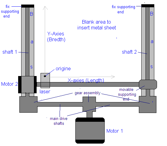
As shown in above figure, there are two stepper motors one is to move laser horizontally (motor 2) and other is to move is vertically (motor 1). The angular motion of motor 1 drives 2 main shafts through suitable gear arrangement. Again this horizontal drive shafts are coupled with two vertical shafts (shaft 1 and shaft 2) through suitable gear arrangement. Coupling used is 1:1 every time. Shaft 1 displaces motor 2 and at the same time on the other hand shaft 2 displaces movable supporting end. So as motor 1 rotates CW / CCW direction, the laser will move up n down (vertically means on Y-Axis). In same manner as motor 2 rotates CW / CCW direction, the laser will move horizontally (in X-Axis).
The relation between angular displacement of motor and linear displacement of laser is given as
5 rotation = 1 inch
So using this equation we can calculate the no of rotation of individual motor after we have the dimension (L X B) of sheet.
E.g. is if we have to cut the sheet of 3′ X 2′ (foot), then 3 foot = 36 inch = 180 rotations. So motor 2 has to rotate 180 rotations. In same manner 2 foot = 24 inch = 120 rotations. So motor 1 has to rotate 120 rotations. So in complete operation as explained above
- Motor 1 will rotate for 180 rotations in CW direction. So laser will cut the sheet in forward upto 3 foot
- Motor 2 will rotate for 120 rotations in CW direction. So laser will move up and cut the sheet upto 2 foot
- Now again motor 1 will rotate for 180 rotations in CCW direction. So laser will cut the sheet in backward upto 3 foot
- And last motor 2 will rotate for 120 rotations in CCW direction. So laser will move down and cut the sheet upto 2 foot
- So finally entire rectangle of 3′ X 2′ is cut from metal sheet.
Note:- The max capacity of the machine is to cut the sheet of 4′ X 5′. The sheet cutting time is approx 10 sec / foot. So to cut the sheet of 3′ x 2′ it will take approx 100 sec.
Now after understanding the operation let us see system block diagram first.
Block Diagram
Block Diagram
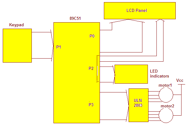
The above figure shows major blocks of laser cutting machine circuit.
Keypad: – It is used to enter dimensions L and B. Its simple 4×3 matrix numeric keypad that has number 0 – 9 keys and one “enter” and one “start” key.
89C51: – For this simple system all you need is one micro-controller that is 89C51. This is the heart of the system that performs all following tasks
- Accepts dimensions entered by user form keypad
- Displays various messages on LCD
- Indicates various events on LEDs
- Rotates both motors as to move laser to calibrated distance
LCD panel:- Is just shows various messages like “Enter X” “Enter Y”, “Press start” etc. To user
LED indicators: – It indicates the rotation of both motors in CW and CCW direction. The purpose it to find out any malfunction of motors or mechanism.
ULN2803: – Its 8 built in Darlington pair, used to provide enough current to stepper motors. Both the stepper motors are of 0.6 A / par phase. So out put of ULN can easily drive them.
Laser cutting machine circuit & Software Program
Laser cutting machine circuit
Connection:- A 4×3 matrix keyboard is connected with P1 as shown. Rows are connected with P1.0 – P1.3 and columns are connected with P1.4 – P1.6. Data lines of LCD (D0-D7) are connected with P0 through 74LS373 latch. Latch is enabling through ALE from 89C51. Three controlling signals RS, RW & E are connected with P2.5, P2.6 & P2.7 respectively. For LEDs (LED1 – LED4) are connected with P2.4 – P2.1 as shown. P3 is used to drive two stepper motors through ULNA chip. A 12 MHz crystal along with 2 33pf capacitors provides clock signal to 89C51. Capacitor C1 is for power on reset feature.
Operation:-
· initially the message “enter x(horizontal) in 2 digits (inch)” is displayed
· After pressing 2 digits as one enters it again message “enter Y (vertical) in 2 digits (inch)” is displayed
· When both X and Y are entered then message “press start” is displayed and system waits for start switch to be pressed
· As one presses start switch the operation will start. Motor 1 will start rotating CW direction. Indicated by LED1. Then motor 2 will rotate CW, indicated by LED2. Then one by one both motors rotate CCW (indicated by LED3 & LED4) and one round is complete.
· Again same above cycle repeats for next sheet cutting.
Now this entire operation is handled by the software program written in C language that is loaded in micro-controller 89C51. So now let us understand it.
Software program: –
writecmd function sends command byte to LCD. It takes one argument byte and sends it to P0
writedata function sends data byte to be displayed on LCD. It also takes one argument byte and sends it to P0
writestr function writes whole string (message) on LCD. It takes pointer as an argument that points address of first character of string. Then through pointer it sends all the character one by one to P0
busy function provides delay after sending command or data byte to LCD
dely function generates delay between two consecutive pulses applied to stepper motor
keydly is key debounce delay of 0.1 sec.
display function takes hex value and first convert it into decimal, then convert it to ASCII. Then display these ASCII characters on LCD
main function handles entire operation.
- It initializes all input output ports
- Initializes LCD and displays messages
- Detects and finds key press and performs corresponding tasks
- It displays the number pressed on LCD as well as rotates both motors in sequential manner.
Project Source Code
###
#include <reg51.h>
#include <string.h>
sbit rs = P2^5; // rs pin of LCD
sbit en =P2^7; // en pin of LCD
sbit rw =P2^6; // rw pin of LCD
sbit led1 = P2^4;
sbit led2 = P2^3;
sbit led3 = P2^2;
sbit led4 = P2^1;
int digit[2];
void writecmd(unsigned char a); // function initializations
void writedata(unsigned char b);
void busy(void);
void writestr(unsigned char *s);
void delay() // delay for stepper mtor pulses
{
int c1;
for(c1=0;c1<8500;c1++);
}
void display(unsigned int z) // to display digits 0-9 on LCD
{
int z1,ASCII[2];
z1=z%10;
ASCII[1]=z1+0x30;
z=z/10;
ASCII[0]=z+0x30;
writedata(ASCII[0]);
writedata(ASCII[1]);
}
void writecmd(unsigned char a)
{
busy();
rs = 0;
rw = 0;
P0 = a;
en = 1;
en = 0;
}
void writedata(unsigned char b)
{
busy();
rs = 1;
rw = 0;
P0 = b;
en = 1;
en = 0;
}
void busy()
{
int c;
for(c=0;c<1500;c++);
}
void writestr(unsigned char *s)
{
unsigned int l,m;
l = strlen(s);
for(m=0;m<l;m++)
{
writedata(*s);
s++;
}
}
keydly()
{
int x,y;
for(x=0;x<100;x++)
for(y=0;y<1000;y++);
}
void main()
{
int t=0,i=0,j,f,p=0,q=0;
unsigned int p2,p1;
P3=0x00; //initilize ports
P2=0x00;
writecmd(0x3C); // initilize LCD
writecmd(0x0E);
back:f=0;
writecmd(0x01); // first display message
if(p==0) writestr("enter x(horizontal)"); // enter X
else
{
writestr("enter y (vertical)"); // then enter Y
p=0;
}
writecmd(0xC0);
writestr("in 2 digits(inch):");
loop:P1=0xF0; // all rows as input and
while(P1==0xF0); // columns as output
while(P1!=0xF0) // wait until no key is pressed
{
P1=0xFE; // when pressed start scanning
if(P1==0xEE) // for enter key
{
if(q==0) // make 2 digit number by
{
p1=digit[0]*10+digit[1]; // multiplying second digit with 10 and adding first digit
q=1;
p=1;
f=1;
}
else
{
p2=digit[0]*10+digit[1]; // second time also make 2 digit number
writecmd(0x01);
writestr("press start");
}
t=1;
i=0;
}
else if(P1==0xDE){writedata(0x30);digit[i]=0;t=1;i++;} // for '0' key display 0 and store digit 0
else if(P1==0xBE) // for start key 's'
{
writecmd(0x80);
writestr("horizontal x= "); // first display X & Y
display(p1);
writestr("inch");
writecmd(0xC0);
writestr("vertical y= ");
display(p2);
writestr("inch ");
p1*=25; // get the final number of rotations
p2*=25;
for(j=0;j<p1;j++) // start rotating motors
{
led1=1; // motor 1 CW
P3=0x01;
delay();
P3=0x02;
delay();
led1=0;
P3=0x04;
delay();
P3=0x08;
delay();
}
for(j=0;j<p2;j++) // motor 2 CW
{
led3=1;
P3=0x10;
delay();
P3=0x20;
delay();
led3=0;
P3=0x40;
delay();
P3=0x80;
delay();
}
for(j=0;j<p1;j++) // motor 1 CCW
{
led2=1;
P3=0x01;
delay();
P3=0x08;
delay();
led2=0;
P3=0x04;
delay();
P3=0x02;
delay();
}
for(j=0;j<p2;j++) // motor 2 CCw
{
led4=1;
P3=0x10;
delay();
P3=0x80;
delay();
led4=0;
P3=0x40;
delay();
P3=0x20;
delay();
}
P3=0x00;
f=1;
t=1;
q=0;
}
if(t==1) break; // get out of loop if key is pressed
P1=0xFD;
if(P1==0xED) {writedata(0x37);t=1;digit[i]=7;i++;} //for '7' key display 7 and store digit 7
else if(P1==0xDD) {writedata(0x38);t=1;digit[i]=8;i++;} // same for all digits
else if(P1==0xBD) {writedata(0x39);t=1;digit[i]=9;i++;}
if(t==1) break;
P1=0xFB;
if(P1==0xEB){writedata(0x34);t=1;digit[i]=4;i++;}
else if(P1==0xDB) {writedata(0x35);t=1;digit[i]=5;i++;}
else if(P1==0xBB) {writedata(0x36);t=1;digit[i]=6;i++;}
if(t==1) break;
P1=0xF7;
if(P1==0xE7){writedata(0x31);digit[i]=1;t=1;i++;}
else if(P1==0xD7) {writedata(0x32);t=1;digit[i]=2;i++;}
else if(P1==0xB7) {writedata(0x33);t=1;digit[i]=3;i++;}
if(t==1) break;
}
keydly(); // key debounce delay
t=0; // reset keypress flag
if(f==0) goto loop; // jump back to enter new digits
else goto back;
}
###
Circuit Diagrams

Filed Under: Electronic Projects

Questions related to this article?
👉Ask and discuss on Electro-Tech-Online.com and EDAboard.com forums.
Tell Us What You Think!!
You must be logged in to post a comment.