Engineers Garage

  • Electronics Projects and Tutorials
    • Electronic Projects
      • Arduino Projects
      • AVR
      • Raspberry pi
      • ESP8266
      • BeagleBone
      • 8051 Microcontroller
      • ARM
      • PIC Microcontroller
      • STM32
    • Tutorials
      • Audio Electronics
      • Battery Management
      • Brainwave
      • Electric Vehicles
      • EMI/EMC/RFI
      • Hardware Filters
      • IoT tutorials
      • Power Tutorials
      • Python
      • Sensors
      • USB
      • VHDL
    • Circuit Design
    • Project Videos
    • Components
  • Articles
    • Tech Articles
    • Insight
    • Invention Stories
    • How to
    • What Is
  • News
    • Electronic Product News
    • Business News
    • Company/Start-up News
    • DIY Reviews
    • Guest Post
  • Forums
    • EDABoard.com
    • Electro-Tech-Online
    • EG Forum Archive
  • DigiKey Store
    • Cables, Wires
    • Connectors, Interconnect
    • Discrete
    • Electromechanical
    • Embedded Computers
    • Enclosures, Hardware, Office
    • Integrated Circuits (ICs)
    • Isolators
    • LED/Optoelectronics
    • Passive
    • Power, Circuit Protection
    • Programmers
    • RF, Wireless
    • Semiconductors
    • Sensors, Transducers
    • Test Products
    • Tools
  • Learn
    • eBooks/Tech Tips
    • Design Guides
    • Learning Center
    • Tech Toolboxes
    • Webinars & Digital Events
  • Resources
    • Digital Issues
    • EE Training Days
    • LEAP Awards
    • Podcasts
    • Webinars / Digital Events
    • White Papers
    • Engineering Diversity & Inclusion
    • DesignFast
  • Guest Post Guidelines
  • Advertise
  • Subscribe

Insight – How 8 Pin DPDT Switch works

By Ashutosh Bhatt July 25, 2011

 
DPDT stands for Double Pole Double Throw switch. By using this we can change the polarity of the applied voltage. It is used in situations where we need different outputs. It has 3 states ON, OFF, ON. The difference between the two ON states is that the polarity of both the states is opposite with respect to each other. That’s the reason why it can drive a DC motor in both the directions. It can also switch an AC motor but it can’t change the direction of the motor. Since, AC motor will run in the same direction irrespective of the polarity therefore, it can only be used for switching ON and OFF an AC motor but not for changing its direction.
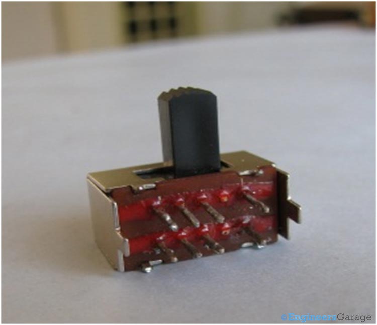
 
Image of Double Pole Double Throw Switch
 
Fig. 1: Image of Double Pole Double Throw Switch
 
Diagram of DPDT Switch
 
Fig. 2: Diagram of DPDT Switch
 
Above image shows a diagrammatic representation of DPDT switch.
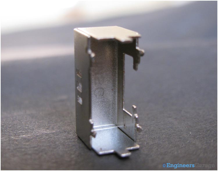
Image Showing 8 DPDT Switch Pins Engraved in Board

Fig. 3: DPDT Switch

Metallic Case

Let’s take a closer look into the DPDT switch. The switch as a whole is enclosed in a metallic case as shown below.

Metallic Case that Holds the DPDT Switch

Fig. 4: Metallic Case that Holds the DPDT Switch

Plastic Casing

There are 3 holes in the metallic case. These holes are used to hold the switch in a particular state. This is done by using a ball bearing and spring which is explained later. The state of the switch is changed by a slider whose image is shown below.
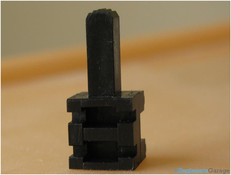
DPDT switch Slider

Fig. 5: DPDT switch Slider

Slider Mechanism

There is ball bearing coming out of the slider. This ball bearing along with the spring, which pushes it outwards fits itself into the holes of the metallic case.  So, by using them the switch attains different states. Hence, the ball remains in three different holes corresponding to three different states.
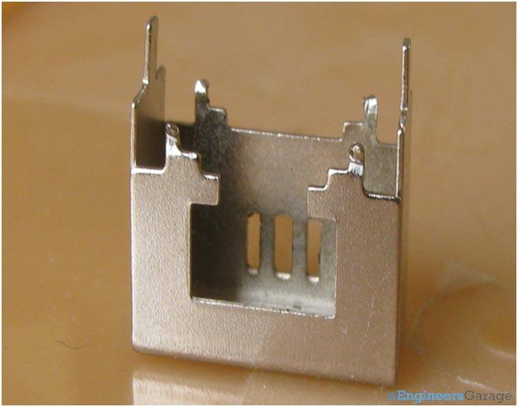
Image Showing the Holes in Metallic Case

Fig. 6: Image Showing the Holes in Metallic Case

Pins

There are 8 pins provided in this DPDT switch. These 8 pins are engraved in a board like structure. These pins are connected inside to metallic plate like structure. These plates connection in different configurations results in change in the polarity. These 8 pins are engraved in the board which is shown below.

Image Showing 8 DPDT Switch Pins Engraved in Board

Fig. 7: Image Showing 8 DPDT Switch Pins Engraved in Board

Metallic Plates

Inside this board these pins are connected to a thin metallic plate like structure. These plate like structures when connected to each other in different configuration changes the polarity. The image of these plates is shown below.

Image Showing 8 DPDT Switch Pins Engraved in Board

Fig. 8: Eight Metallic Plates for each of 8 Pins of DPDT Switch

Clips

er = When the slider is moved from outside different connections of these plates are formed. The connections are formed by connecting these plates . For making different connections sliding clips are used which are shown below.
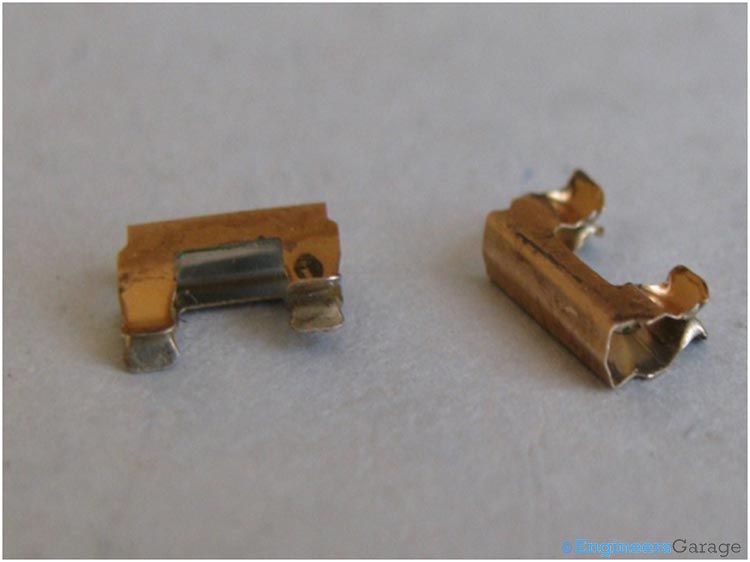
Sliding Clips used to Enable Movement of Slider
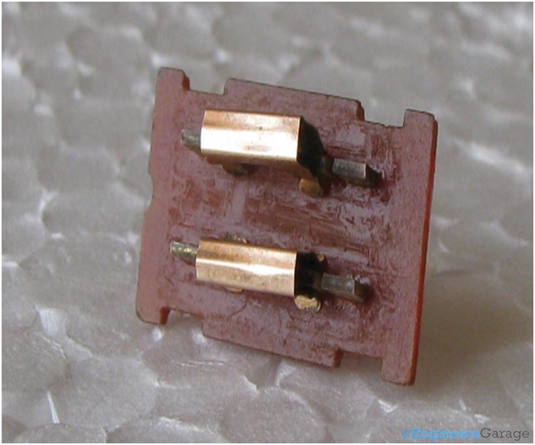
 

Fig. 9: Sliding Clips used to Enable Movement of Slider


Image Showing How Clips are used to Make Contacts Between Plates
 
Fig. 10: Image Showing How Clips are used to Make Contacts Between Plates
 
Image indicating how clips are used to make contacts between plates.
These clips are fitted into the space provided in the slider. These clips, when slide over the metallic plates, result in different configurations. These different configurations give different polarity.

Filed Under: Insight
Tagged With: 8 pin dpdt switch, dpdt, dpdt switch, metal clip, switch
 

Next Article

← Previous Article
Next Article →

Questions related to this article?
👉Ask and discuss on Electro-Tech-Online.com and EDAboard.com forums.


Tell Us What You Think!! Cancel reply

You must be logged in to post a comment.

EE TECH TOOLBOX

“ee
Tech Toolbox: Internet of Things
Explore practical strategies for minimizing attack surfaces, managing memory efficiently, and securing firmware. Download now to ensure your IoT implementations remain secure, efficient, and future-ready.

EE Learning Center

EE Learning Center
“engineers
EXPAND YOUR KNOWLEDGE AND STAY CONNECTED
Get the latest info on technologies, tools and strategies for EE professionals.

HAVE A QUESTION?

Have a technical question about an article or other engineering questions? Check out our engineering forums EDABoard.com and Electro-Tech-Online.com where you can get those questions asked and answered by your peers!


RSS EDABOARD.com Discussions

  • MCU identification?
  • GanFet power switch starts burning after 20 sec
  • problem identifying pin purpose on PMA5-83-2WC+ amplifier
  • AC amplifier, transistor with bias network
  • modelsim not run the clock long enough

RSS Electro-Tech-Online.com Discussions

  • LED circuit for 1/6 scale diorama
  • Can I use this charger in every country?
  • Electronic board faulty?!?
  • using a RTC in SF basic
  • An Update On Tarrifs

Featured – Designing of Audio Amplifiers part 9 series

  • Basics of Audio Amplifier – 1/9
  • Designing 250 Milli Watt Audio Power Amplifier – 2/9
  • Designing 1 Watt Audio Power Amplifier – 3/9
  • Designing a Bass Boost Amplifier – 4/9
  • Designing a 6 Watt Car Audio Amplifier – 5/9
  • Design a low power amplifier for headphones- 6/9

Recent Articles

  • Fischer connector system adds ratchet locking system designed for 300g shock resistance
  • Littelfuse introduces tactile switch with enhanced bracket peg design for mounting strength
  • Infineon releases GaN switch with monolithic bidirectional design
  • Sienna Semiconductor data converters feature sample rates from 20 to 250 Msps
  • Delta’s 5,500 W power supplies achieve 97.5% energy efficiency for AI servers

EE ENGINEERING TRAINING DAYS

engineering

Submit a Guest Post

submit a guest post
Engineers Garage
  • Analog IC TIps
  • Connector Tips
  • Battery Power Tips
  • DesignFast
  • EDABoard Forums
  • EE World Online
  • Electro-Tech-Online Forums
  • EV Engineering
  • Microcontroller Tips
  • Power Electronic Tips
  • Sensor Tips
  • Test and Measurement Tips
  • 5G Technology World
  • Subscribe to our newsletter
  • About Us
  • Contact Us
  • Advertise

Copyright © 2025 WTWH Media LLC. All Rights Reserved. The material on this site may not be reproduced, distributed, transmitted, cached or otherwise used, except with the prior written permission of WTWH Media
Privacy Policy

Search Engineers Garage

  • Electronics Projects and Tutorials
    • Electronic Projects
      • Arduino Projects
      • AVR
      • Raspberry pi
      • ESP8266
      • BeagleBone
      • 8051 Microcontroller
      • ARM
      • PIC Microcontroller
      • STM32
    • Tutorials
      • Audio Electronics
      • Battery Management
      • Brainwave
      • Electric Vehicles
      • EMI/EMC/RFI
      • Hardware Filters
      • IoT tutorials
      • Power Tutorials
      • Python
      • Sensors
      • USB
      • VHDL
    • Circuit Design
    • Project Videos
    • Components
  • Articles
    • Tech Articles
    • Insight
    • Invention Stories
    • How to
    • What Is
  • News
    • Electronic Product News
    • Business News
    • Company/Start-up News
    • DIY Reviews
    • Guest Post
  • Forums
    • EDABoard.com
    • Electro-Tech-Online
    • EG Forum Archive
  • DigiKey Store
    • Cables, Wires
    • Connectors, Interconnect
    • Discrete
    • Electromechanical
    • Embedded Computers
    • Enclosures, Hardware, Office
    • Integrated Circuits (ICs)
    • Isolators
    • LED/Optoelectronics
    • Passive
    • Power, Circuit Protection
    • Programmers
    • RF, Wireless
    • Semiconductors
    • Sensors, Transducers
    • Test Products
    • Tools
  • Learn
    • eBooks/Tech Tips
    • Design Guides
    • Learning Center
    • Tech Toolboxes
    • Webinars & Digital Events
  • Resources
    • Digital Issues
    • EE Training Days
    • LEAP Awards
    • Podcasts
    • Webinars / Digital Events
    • White Papers
    • Engineering Diversity & Inclusion
    • DesignFast
  • Guest Post Guidelines
  • Advertise
  • Subscribe