You may know how to drive or you are just like me who always tag along as side kick, but there is one part of automobile that is voluntary known to each one of us “Speedometer”. You may not be driving but one step on accelerator by the driver and you are squirming on your seat just as the needle on the meter. Ha!
We have never really thought how does a needle move on the meter? What makes the number change on odometer? We look at speedometer but never really notice it. But not anymore join me in this insight to learn all about speedometer. Right from its structure, to wiring to calibration everything is devised with perfection. The moment you start your vehicle the speedometer starts working.
Let’s begin our insight with the external part.
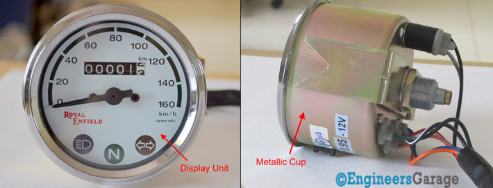
Fig. 1: Image Showing External Side of A Typical Analog Speedometer
The external view shows a circular display unit placed on a metallic cup. Display system is surrounded by chrome metal to provide it an extra finish.

Fig. 2: Rear Side Outer View of Analog Speedometer

Fig. 3: Rubber Cables and Holder Present In An Analog Speedometer
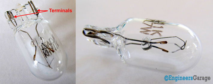
Fig. 4: Image Showing Bulbs Used in Analog Speedometer
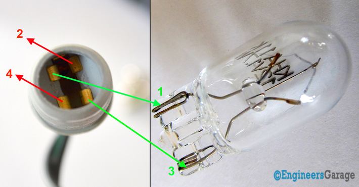
Fig. 5: Pictures Showing Copper Terminals Present In Analog Speedometer Bulbs
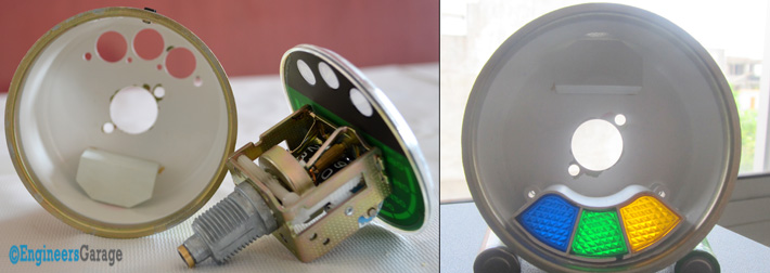
Fig. 6: Image Showing Colored Relflectors Present In An Analog Speedometer

Fig. 7: Analong Speedometer Driver Cable
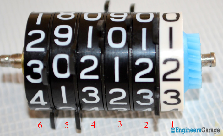
Fig. 8: Spiral Groove Holding Driver Cable

Fig. 9: Cable Present Inside Spiral Groove
Eddy currents- are electric current generated in the conductors (aluminum cup in speedometer) due to changing magnetic field (produced by magnet in the cup). The circulating currents have inductance and thus induce magnetic fields. These fields can cause attraction, repulsion, drag and heating effects. The stronger the applied magnetic fields faster and greater are the effects. Now let’s move ahead and understand how eddy current comes into picture of speedometer assembly
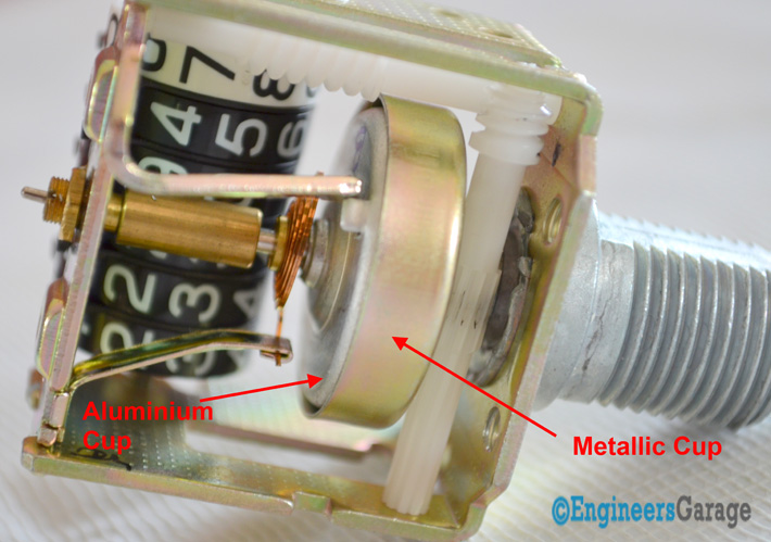
Fig. 10: Picture Showing How Eddy Current Moves Inside Speedometer Assembly

Fig. 11: Image Showing Details of Speed Cup In An Analog Speedometer

Fig. 12: Speed Cup Separated From Magnet
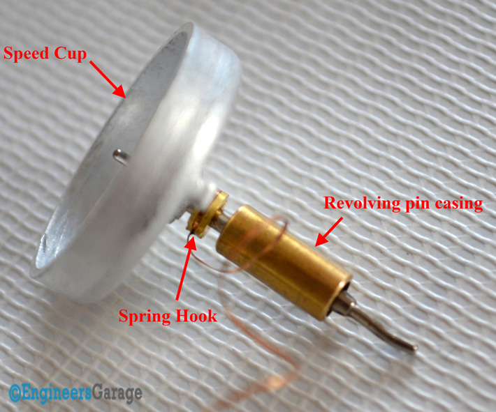
Fig. 13: Image Explaining Various Parts of Speed Cup
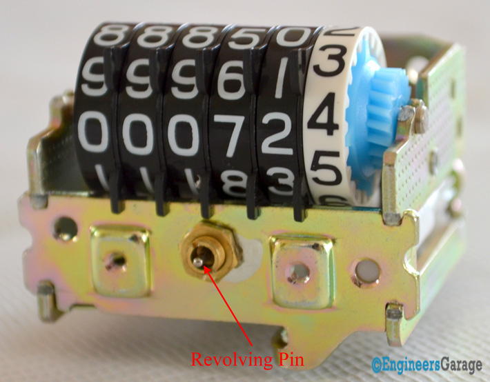
Fig. 14: Cross Sectional View of Revolving Pin Inside Speedometer
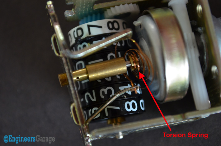
Fig. 15: Torsion Spring Position Near The Revolving Pin
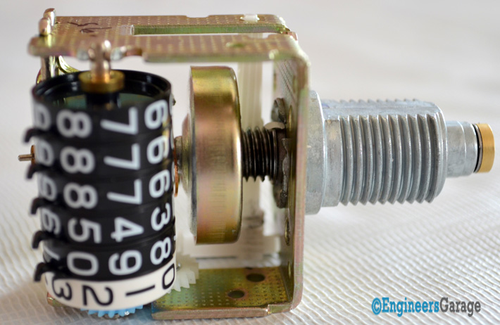
Fig. 16: Image Explaining Working of Revolving Pin
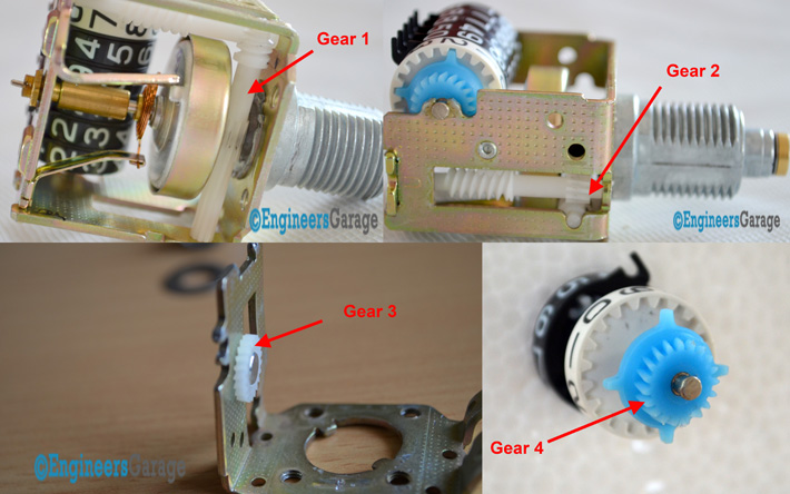
Fig. 17: Image Showing Position and Working of Gears In Speedometer

Fig. 18: Image Showing Rear Part of Ring 1 (Left) and Front End of Ring 2 (Right)

Fig. 19: Image Showing Arrangement of Consecutive Rings

Fig. 20: Odometer Assembly In Speedometer
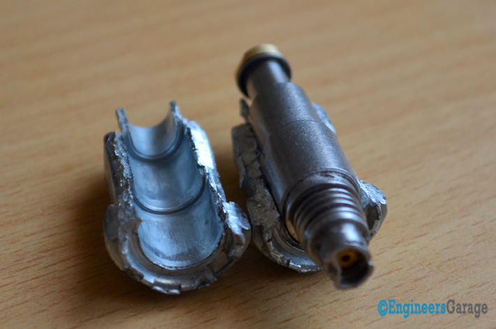
Fig. 21: Image Showing Grooves Present Around Rings
Filed Under: Insight, More Editor's Picks


Questions related to this article?
👉Ask and discuss on Electro-Tech-Online.com and EDAboard.com forums.
Tell Us What You Think!!
You must be logged in to post a comment.