
Fig. 1: Image of Circular Power Connectors
In industries, transmitting error free signal and data is very crucial as a small variation may affect the processes by a large extent. Hence, interfacing the wires carrying such information to the subsequent devices becomes crucial. Serving this critical purpose are Circular Power connectors that take care ofsignal accuracy in multiple signal and data lines through a multi-pin structure. These connectors are configured from a 4-pin to a 6-pin mode depending on the requirement.
These connectors are easy to mount on any device and are resistant from environmental influences. Read this Insight to know what is inside these devices!

Fig. 2: External Structure of Circular Power Connector
External View: Image 02 depicts a conventional 4-pin power connector. A tough ally structure, the structure is designed to be able to tolerate high power inputs as well as make them tolerable towards electromagnetic radiations.
In the image, the end towards the right is where wires are inserted into the connector and towards the left are output pins which can be soldered.
Output Pins & Input Terminal
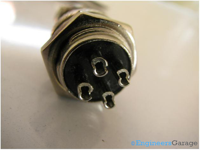
Fig. 3: Output Pins and their Structure
Output Pins: The shape of the output pins are worth noticing. They have a cylindrical structure with crescent shapes cut at their .This allows easy connections.

Fig. 4: Input Terminal
Input Terminal: The input terminal is an open cylindrical end having a ring grooving which can be opened through the screws connected at its circumference.
Dissembled Connector & Pin Placement

Fig. 5: Dissembled Connector to Facilitate Wire Insertion
The screws are opened in order to allow reasonable wire insertion into the connector.
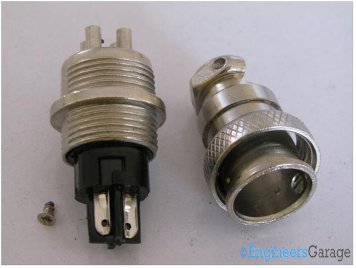
Fig. 6: Connector Part to Connect Wires
Dissembled Connector: Once dissembled, the connector’s ends where the input wires fix are seen. Usually, there are two ways for connecting wires: clinging–them-on or soldering; the latter is used here.
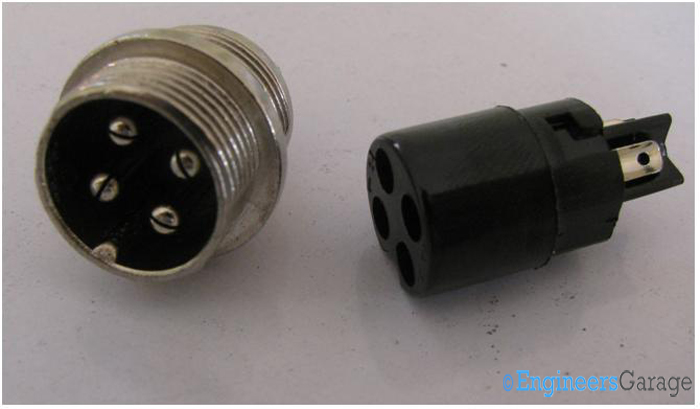
Fig. 7: Arrangement for Pin Placement
Pin Placement: The pins are placed on a plastic molding which is removed from the alloy structure as shown in the image above. There are cut sections on other side of the plastic molding indicating it to be the female counterpart of the connector assembly. Also, pins are found to be located on the alloy region of the connector.
Output Pins: Structure & Shape
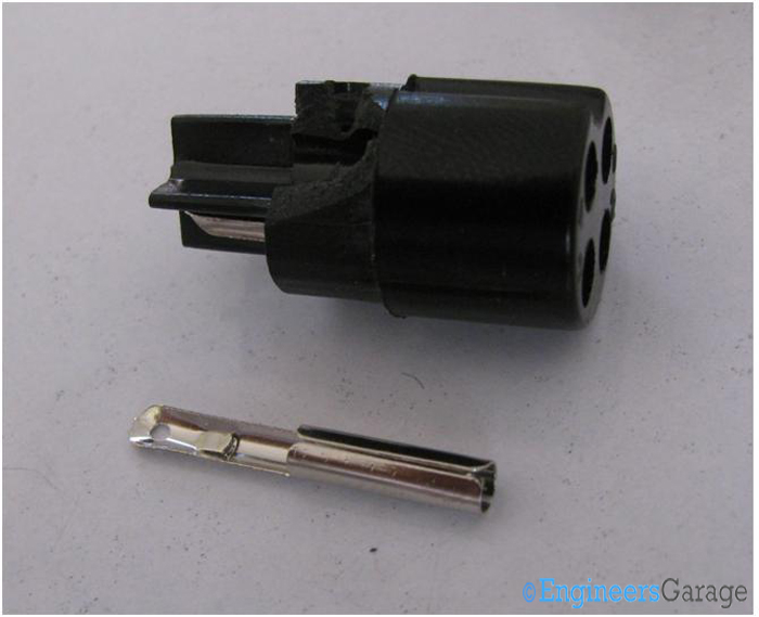
Fig. 8: Shape of Pin and Plastic Holding
Shape of Pins: The pins placed inside the plastic moldings are plucked out to observe their other end. Flattened to connect from one end, the pins form an open ended cylindrical shape so that they get plugged into the male counterparts located in the alloy structure.
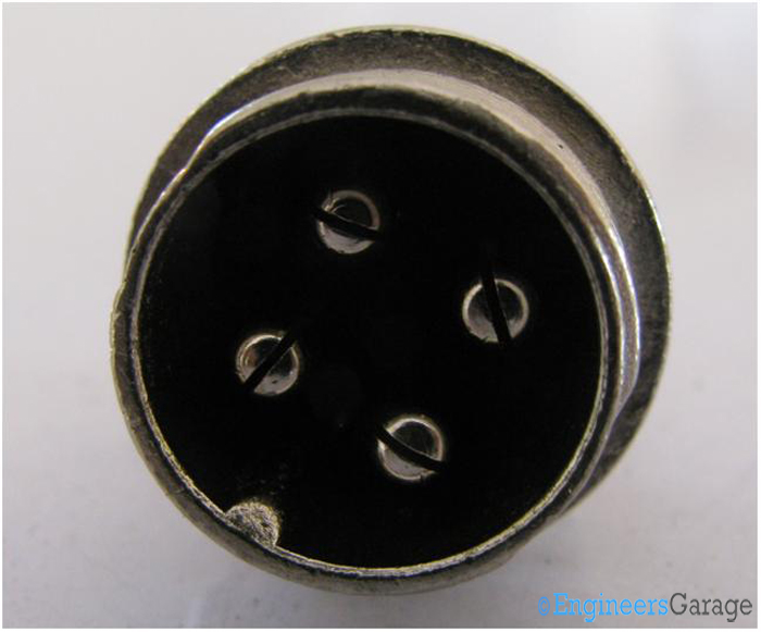
Fig. 9: Plastic Molding for Plugging Male Pins
Male Pins: The region where plastic molding is plugged is shown above. Two pairs of male connector pins are placed in the plastic moldings. These connector pins terminate at the other end of the connector from where they are connected to the device or are soldered.

Fig. 10: Image Showing Output Pin Structure
Output Pin Structure: These pins pose a structure similar to the one of a household plug. They have slight cut sections in the middle on the end where plastic molding plugs in. On the other end, there are open sections through which the connector interfaces with other devices or gets soldered.
Filed Under: Insight


Questions related to this article?
👉Ask and discuss on Electro-Tech-Online.com and EDAboard.com forums.
Tell Us What You Think!!
You must be logged in to post a comment.