Engineers Garage

  • Electronics Projects and Tutorials
    • Electronic Projects
      • Arduino Projects
      • AVR
      • Raspberry pi
      • ESP8266
      • BeagleBone
      • 8051 Microcontroller
      • ARM
      • PIC Microcontroller
      • STM32
    • Tutorials
      • Audio Electronics
      • Battery Management
      • Brainwave
      • Electric Vehicles
      • EMI/EMC/RFI
      • Hardware Filters
      • IoT tutorials
      • Power Tutorials
      • Python
      • Sensors
      • USB
      • VHDL
    • Circuit Design
    • Project Videos
    • Components
  • Articles
    • Tech Articles
    • Insight
    • Invention Stories
    • How to
    • What Is
  • News
    • Electronic Product News
    • Business News
    • Company/Start-up News
    • DIY Reviews
    • Guest Post
  • Forums
    • EDABoard.com
    • Electro-Tech-Online
    • EG Forum Archive
  • DigiKey Store
    • Cables, Wires
    • Connectors, Interconnect
    • Discrete
    • Electromechanical
    • Embedded Computers
    • Enclosures, Hardware, Office
    • Integrated Circuits (ICs)
    • Isolators
    • LED/Optoelectronics
    • Passive
    • Power, Circuit Protection
    • Programmers
    • RF, Wireless
    • Semiconductors
    • Sensors, Transducers
    • Test Products
    • Tools
  • Learn
    • eBooks/Tech Tips
    • Design Guides
    • Learning Center
    • Tech Toolboxes
    • Webinars & Digital Events
  • Resources
    • Digital Issues
    • EE Training Days
    • LEAP Awards
    • Podcasts
    • Webinars / Digital Events
    • White Papers
    • Engineering Diversity & Inclusion
    • DesignFast
  • Guest Post Guidelines
  • Advertise
  • Subscribe

Insight – How Computer Optical Mouse works

By Ashutosh Bhatt June 15, 2011


The replacement of conventional ball mouse by the technically superior optical mouse is not hidden to anybody. An optical mouse works by having a low resolution camera inside it which takes around 1500 to 6000 pictures per second of the surface beneath it, and by analyzing these images, it calculate the position, speed and movement of the mouse.
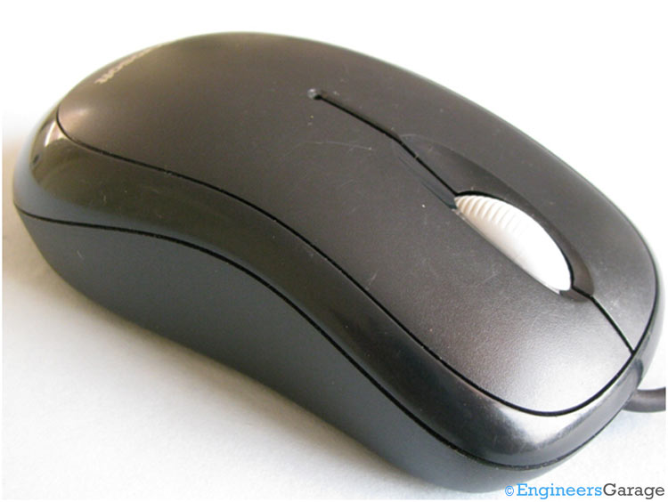
Computer optical mouse

Fig. 1: Computer Optical Mouse

 
Rear view of optical mouse
 
Fig. 2: Rear View of Optical Mouse
 
The above images are showing different views of an optical mouse.

Electronic Components

 Image showing various electronic components of optical mouse
 
Fig. 3: Image Showing Various Electronic Components of Optical Mouse
 
On removing the outer cover, you can have a glimpse of majority of the components used in mouse.
 
 Light reflector at bottom of mouse
 
Fig. 4: Light Reflector at Bottom of Mouse
 
The plastic covering shown is used to reflect and concentrate all the light rays at bottom of the camera.

Light Scatterer & LED

Lens used to reflect LED light to surface
 
Fig. 5: Lens Used to Reflect LED Light to Surface
 
This special shaped lens is designed to reflect the LED light to surface.
 
Side view of lens
 
Fig. 6: Side View of Lens
 
The LED shown in the image below is used to flash lights on the surface that bounce back to the camera in order to take clear picture of the surface.

Optical Mouse Sensor

IC sensor of optical mouse
 
Fig. 7: IC Sensor of Optical Mouse
 
The IC shown in above image is an optical mouse sensor. It works on Optical navigation technology which measures changes in position by optically acquiring surface images and then determining the direction and distance of movement.
The above IC contains an Image Acquisition System (IAS), a Digital Signal Processor (DSP) and a two wire serial port. IAS takes images of the surface via an in house lens. These images are processed by DSP and the resultant coordinates are continuously stored which can be extracted using the serial interface format.

Communication IC

 IC A2611D and its various functions
 
Fig. 8: IC A2611D and its Various Functions
 
You can see another IC (A2611D) in the image above which does the following function:
1.      It takes input from the Optical Mouse Sensor through I2C protocol.
2.      Generate clock for synchronization.
3.      Takes inputs from left, right and middle buttons of the mouse and accordingly sends data to the PC.
4.      Works as voltage regulator.
5.      The IC works as USB Transceiver i.e. at a time it can transmit & receives data from USB.

Scroll Mechanism
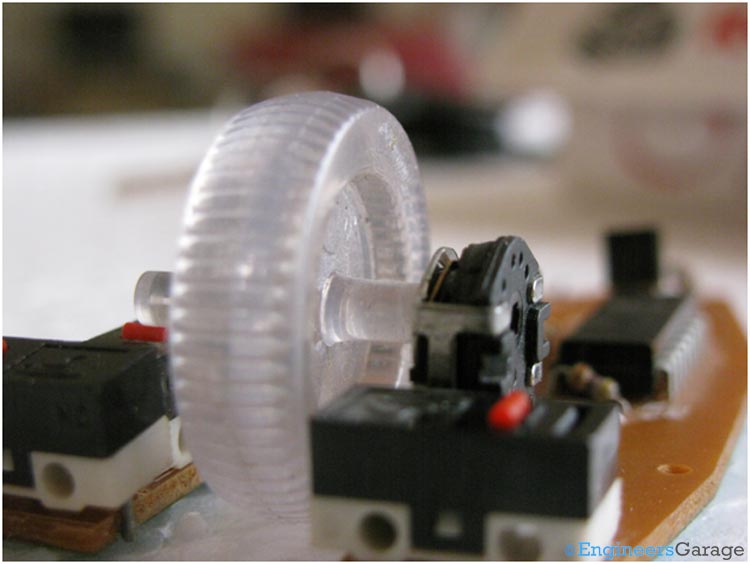
Scroll mechanism of optical mouse
 
Fig. 9: Scroll Mechanism of Optical Mouse
 
When we rotate the wheel of a mouse, the potentiometer attached with the wheel as shown in the picture above also rotates, thereby producing different output voltages. The potentiometer works as a sensor and the output signal which is a variable voltage after processing is given to the PC.

Potentiometer

Optical mouse potentiometer---side view
 
Fig. 10: Optical Mouse Potentiometer—Side View
 
Optical mouse potentiometer---second view
 
Fig. 11: Optical Mouse Potentiometer—Second View
 
The above image shows the internal structure of the potentiometer attached with the mouse wheel.

Click Mechanism
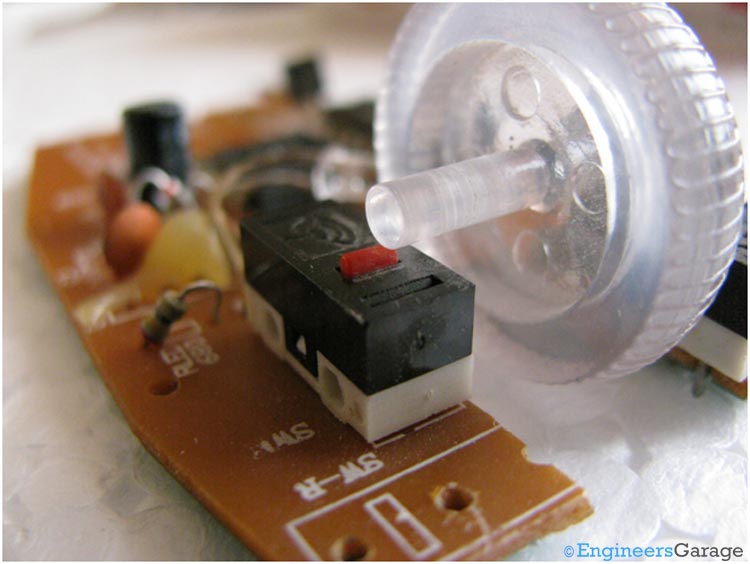
 Image showing click mechanism of optical mouse
 
Fig. 12: Image Showing Click Mechanism of Optical Mouse
 
The red button shown in the above image is the center click of the mouse.
 
Internal architecture of mouse click swithches
 
Fig. 13: Internal Architecture of Mouse Click Switches
 
The internal architecture and working of the switches used for mouse click is shown in the images below.

Switch Structure

Flexible metal plate inside the mouse click switch
 
Fig. 14: Flexible Metal Plate Inside the Mouse Click Switch
 
When a button is clicked, a flexible metal plate is pressed which shorts the two points of the circuit that detects the mouse click.
 
Working: When a mouse is connected with the computer, a red LED starts glowing. This light is focused on the surface beneath the mouse by a special type of lens (HDNS-2100). The reflected light falls back to the camera integrated in Optical Mouse Sensor.  The camera takes images of the surface with a frequency in the range of 1500 to 6000 images per second to calculate the position of mouse. These images are processed by Digital Signal Processor and resultant co-ordinates are sent to IC A2611D via serial data transmission. Another IC (A2611D) takes the serial input from and image sensor and the buttons of the mouse, converts it to USB protocols and sends it to the PC. The driver of the mouse installed in the computer receives the co-ordinates and makes the cursor move accordingly.  

Filed Under: Insight
Tagged With: computer, computer mouse, mouse, optical mouse
 

Next Article

← Previous Article
Next Article →

Questions related to this article?
👉Ask and discuss on EDAboard.com and Electro-Tech-Online.com forums.


Tell Us What You Think!! Cancel reply

You must be logged in to post a comment.

EE TECH TOOLBOX

“ee
Tech Toolbox: Internet of Things
Explore practical strategies for minimizing attack surfaces, managing memory efficiently, and securing firmware. Download now to ensure your IoT implementations remain secure, efficient, and future-ready.

EE Learning Center

EE Learning Center
“engineers
EXPAND YOUR KNOWLEDGE AND STAY CONNECTED
Get the latest info on technologies, tools and strategies for EE professionals.

HAVE A QUESTION?

Have a technical question about an article or other engineering questions? Check out our engineering forums EDABoard.com and Electro-Tech-Online.com where you can get those questions asked and answered by your peers!


RSS EDABOARD.com Discussions

  • GanFet power switch starts burning after 20 sec
  • RF-DC rectifier impedance matching
  • Inverting OpAmp - basic circuit question
  • 12VAC to 12VDC 5A on 250ft 12AWG
  • Precision CAD Drafting Services for Architectural & Engineering Projects

RSS Electro-Tech-Online.com Discussions

  • LED circuit for 1/6 scale diorama
  • stud mount Schottky diodes
  • Hi Guys
  • using a RTC in SF basic
  • Can I use this charger in every country?

Featured – Designing of Audio Amplifiers part 9 series

  • Basics of Audio Amplifier – 1/9
  • Designing 250 Milli Watt Audio Power Amplifier – 2/9
  • Designing 1 Watt Audio Power Amplifier – 3/9
  • Designing a Bass Boost Amplifier – 4/9
  • Designing a 6 Watt Car Audio Amplifier – 5/9
  • Design a low power amplifier for headphones- 6/9

Recent Articles

  • Fischer connector system adds ratchet locking system designed for 300g shock resistance
  • Littelfuse introduces tactile switch with enhanced bracket peg design for mounting strength
  • Infineon releases GaN switch with monolithic bidirectional design
  • Sienna Semiconductor data converters feature sample rates from 20 to 250 Msps
  • Delta’s 5,500 W power supplies achieve 97.5% energy efficiency for AI servers

EE ENGINEERING TRAINING DAYS

engineering

Submit a Guest Post

submit a guest post
Engineers Garage
  • Analog IC TIps
  • Connector Tips
  • Battery Power Tips
  • DesignFast
  • EDABoard Forums
  • EE World Online
  • Electro-Tech-Online Forums
  • EV Engineering
  • Microcontroller Tips
  • Power Electronic Tips
  • Sensor Tips
  • Test and Measurement Tips
  • 5G Technology World
  • Subscribe to our newsletter
  • About Us
  • Contact Us
  • Advertise

Copyright © 2025 WTWH Media LLC. All Rights Reserved. The material on this site may not be reproduced, distributed, transmitted, cached or otherwise used, except with the prior written permission of WTWH Media
Privacy Policy

Search Engineers Garage

  • Electronics Projects and Tutorials
    • Electronic Projects
      • Arduino Projects
      • AVR
      • Raspberry pi
      • ESP8266
      • BeagleBone
      • 8051 Microcontroller
      • ARM
      • PIC Microcontroller
      • STM32
    • Tutorials
      • Audio Electronics
      • Battery Management
      • Brainwave
      • Electric Vehicles
      • EMI/EMC/RFI
      • Hardware Filters
      • IoT tutorials
      • Power Tutorials
      • Python
      • Sensors
      • USB
      • VHDL
    • Circuit Design
    • Project Videos
    • Components
  • Articles
    • Tech Articles
    • Insight
    • Invention Stories
    • How to
    • What Is
  • News
    • Electronic Product News
    • Business News
    • Company/Start-up News
    • DIY Reviews
    • Guest Post
  • Forums
    • EDABoard.com
    • Electro-Tech-Online
    • EG Forum Archive
  • DigiKey Store
    • Cables, Wires
    • Connectors, Interconnect
    • Discrete
    • Electromechanical
    • Embedded Computers
    • Enclosures, Hardware, Office
    • Integrated Circuits (ICs)
    • Isolators
    • LED/Optoelectronics
    • Passive
    • Power, Circuit Protection
    • Programmers
    • RF, Wireless
    • Semiconductors
    • Sensors, Transducers
    • Test Products
    • Tools
  • Learn
    • eBooks/Tech Tips
    • Design Guides
    • Learning Center
    • Tech Toolboxes
    • Webinars & Digital Events
  • Resources
    • Digital Issues
    • EE Training Days
    • LEAP Awards
    • Podcasts
    • Webinars / Digital Events
    • White Papers
    • Engineering Diversity & Inclusion
    • DesignFast
  • Guest Post Guidelines
  • Advertise
  • Subscribe