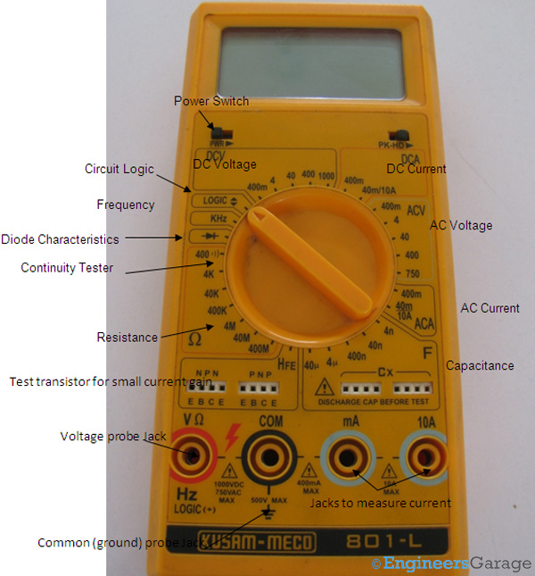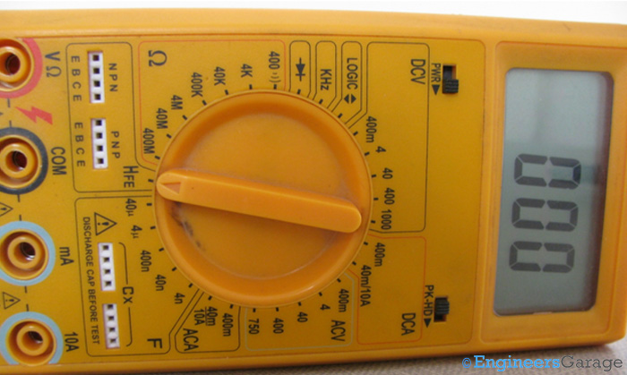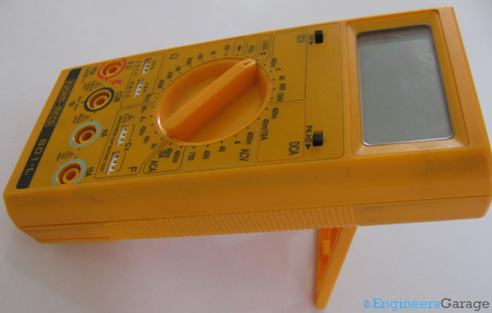
Figure 1. A digital multimeter.
As the name suggests, multimeters are measuring instruments that calculate multiple circuit characteristics. Making them digital provides exact outputs. So, unlike their analog counterparts, there’s no needle to interpret, eliminating potential reading errors.
But how are digital meters more advanced than their predecessors? What internal circuitry enables such rapid calculations? Can you hook one to a circuit and take readings on the fly? A multimeter does just that. Let’s explore the fundamentals of the multimeter, which serves as a jack-of-all-trades in electrical measurements.
Outer casing

Figure 2. The various parts of a multimeter’s outer structure.
The image above depicts a commonly used multimeter. Encased in durable plastic, this measuring and testing instrument often includes a tilt stand for easy reading.
Every multimeter comes with specifications that define its functions and measurement range. For instance, the one discussed in this insight can measure dc voltage from 400 mV to 1000 V and resistance from 400Ω to 400MΩ. In addition to standard current, voltage, and resistance measurements, this instrument can test logic, measure diode characteristics, analyze transistor gain, and even measure frequency. A built-in buzzer emits a sound when the circuit is functional to check circuit continuity.
Accuracy and precision
Accuracy is one of the most critical factors in a multimeter’s specifications. It defines how close the measured result is to the actual value. The lower the deviation margin, the higher the accuracy. For example, a multimeter measuring voltage with an accuracy of ±0.6V will provide more precise readings than one with ±0.8V.
Multimeters are often evaluated based on their accuracy, as higher precision is essential for reliable measurements in electrical and electronic applications.
Input ports and battery

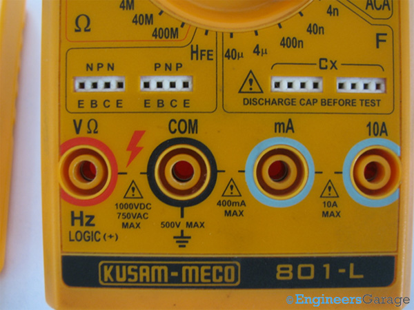
Figure 3. The multimeter’s ports.
Most multimeters have a volt port and a common port where the probes are attached. However, additional ports are provided for measuring current. The inclusion of a milliampere current port requires protective circuitry, as accidental exposure to high currents can damage the instrument and potentially pose a safety risk to the user.

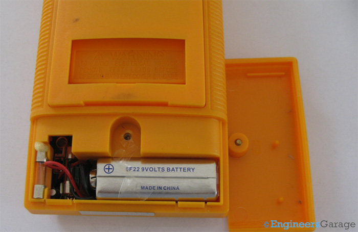
Figure 4. The battery and fuse, which are encased in the back of a multimeter.
The rear of the multimeter houses a 9V battery and a fuse. Positioned between the battery and input ports, the fuse acts as a circuit protector, cutting off the measuring process when the applied input exceeds the safe operating range. The battery and fuse are secured by a single-screw flap, allowing for quick replacement to minimize interruptions during use. Additionally, an extra fuse is provided for convenience.
The internal structure

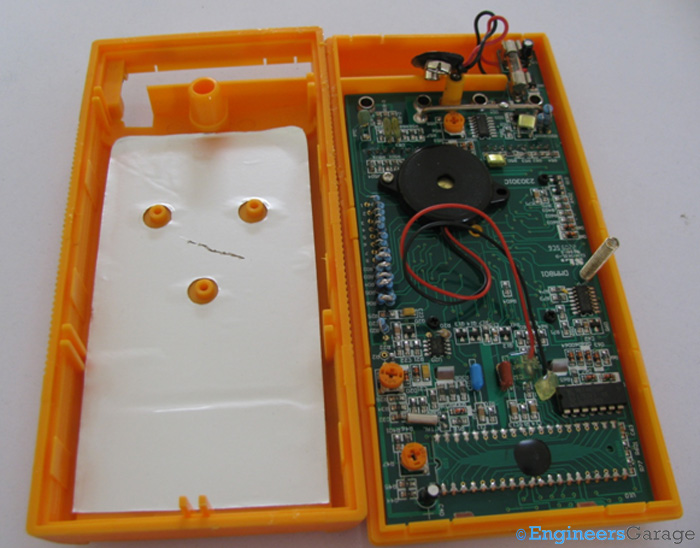
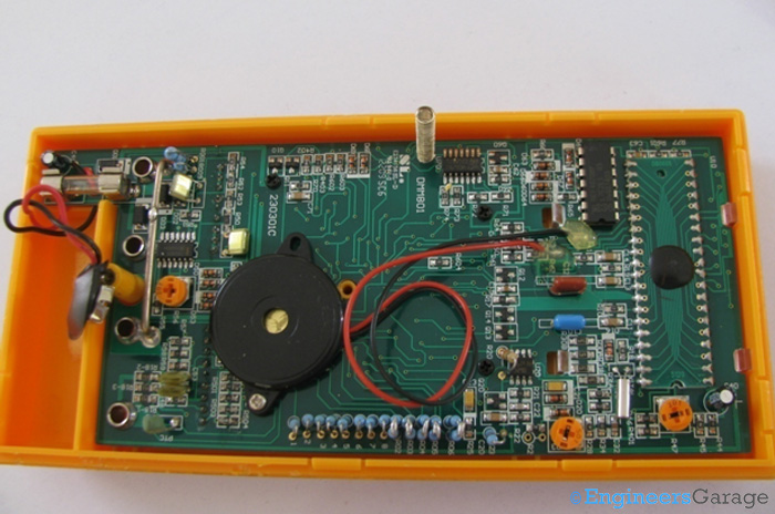
Figure 5. The PCB and circuitry of a multimeter.
The multimeter box does not require screws for opening, as the upper and lower sections are secured with plastic latches. The PCB and circuitry are mounted on the upper section, while the lower section consists of a thin layer of anodized aluminum. This non-conductive layer aids in uniform heat dispersion in cases of high current input to the multimeter.
The PCB

Figure 6. A closer view of the PCB and the circuit arrangement.
The PCB contains a variety of components, including resistors, capacitors, diodes, and integrated circuits (ICs). It also houses the battery, crystal oscillator, PTC, LCD, and buzzer, which is used to test the continuity of the device under test (DuT).
One of the key ICs on the PCB is:
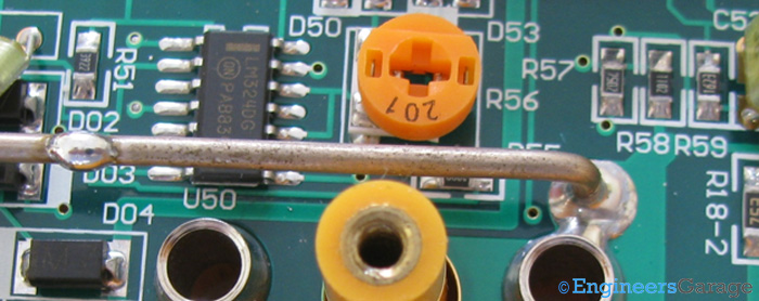
1. LM324DG – A low-power operational amplifier that functions as a comparator. This IC features quad inputs and outputs, operates on a single power supply, and delivers optimized power at low-voltage inputs.

Figure 7. The operational amplifier IC, LM324DG.
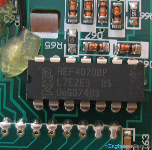
2. HEF4070 – A quadruple exclusive OR (EX-OR) gate IC with 14 pins. It provides four EX-OR functions with high noise immunity and is primarily used as a logic comparator and in parity checkers.

Figure 8. The: 14-pin IC, HEF4070.

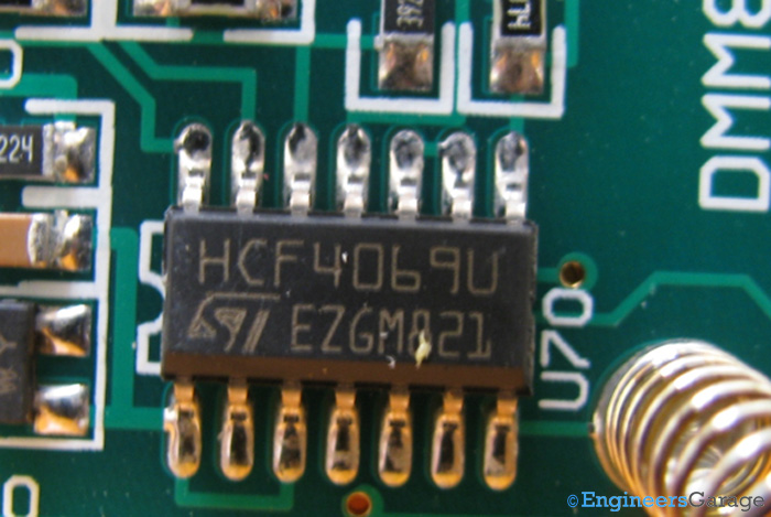
Figure 9. The hex-function Inverter, the HCF4069.

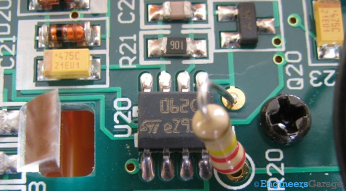
Figure 10. The JFET Op-Amp IC, TL062.
Apart from these ICs, a chip-on-board (COB) IC is also present, which interfaces with the LCD screen and is mounted on the rear of the display.
The range selector: Conducting circular rings and range selection

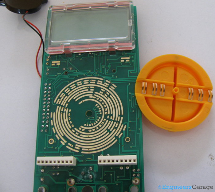
Figure 11. The LCD, PCB, and rotary knob switch.
The PCB is secured to the top casing of the multimeter using screws. An LCD and a rotary knob switch are positioned between the top casing and the PCB. Additionally, the contacts for switching the multimeter on and off are visible. Some multimeters use the rotary switch for power control, while others—like the one in this insight—employ a slider switch for turning the device on and off.
On the other side of the PCB, 11 concentric conducting rings enable circuit connections and disconnections through the rotary knob, which acts as a switch. The ring patterns vary by manufacturer and the multimeter’s functions. None of the rings form a complete circular connection — each is interrupted at some point. These conductive tracks are also greased to ensure smooth rotation of the switch.
The rotation of the switch determines which part of the PCB circuit is activated and which remains inactive.

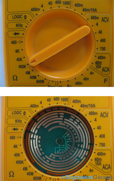
Figure 12. A rotary switch (top) and a ring alignment (bottom).
A clearer view of how these rings align with the function selector can be seen in the image above. Interestingly, the rotary switch does not always contact the rings corresponding to the selected function.
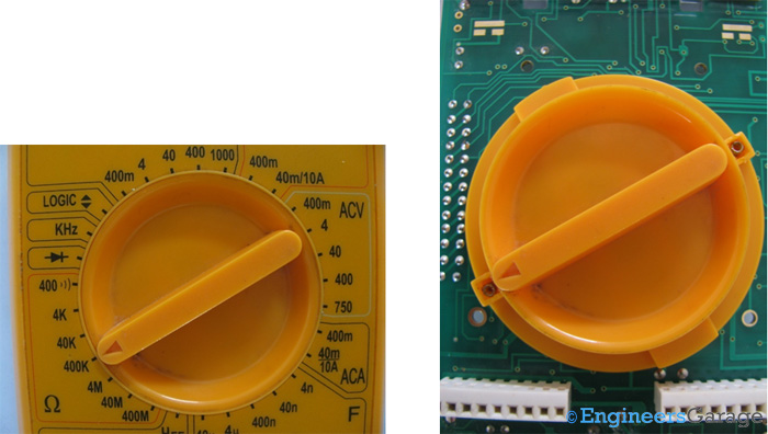
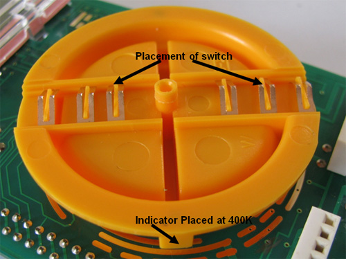
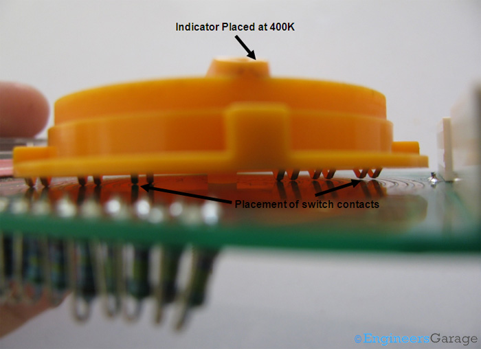
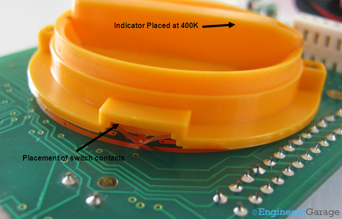
For instance, when the multimeter is set to measure resistance in the 400KΩ range, the placement of the switch contacts can be observed in the images below.

Figure 13. Positioning the rotary switch to measure the 400-K resistance range.

Figure 14. The rotary switch mechanism.

Figure 15. The indicator and corresponding placement of the pins.

Figure 16. The rotary switch positioning of the PCB.

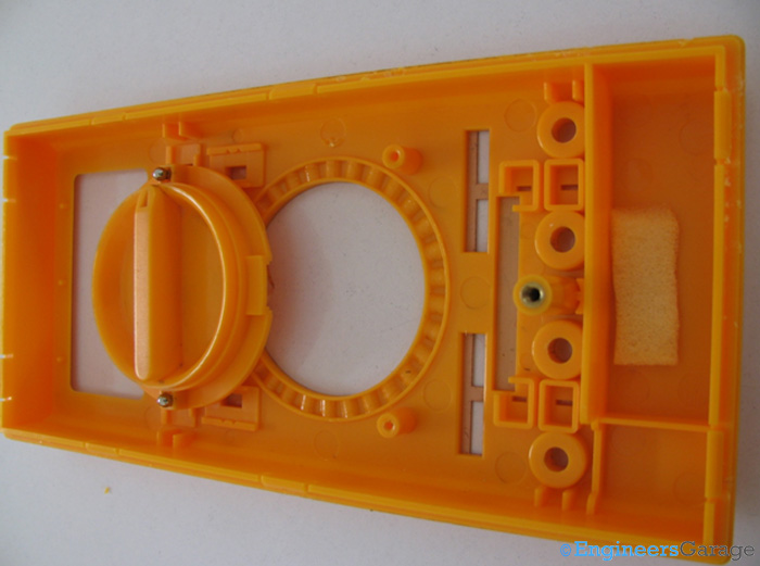
Figure 17. The track on the top casing where the switch is positioned.
To allow smooth rotation of the switch, a track is provided inside the top casing, along with two tiny metal balls. These metal balls assist movement along the track and produce a clicking sound whenever the knob is rotated, confirming that the user has changed the range, function, or both. Using these metal balls over a corrugated track also helps keep the dial in place, ensuring that the selected mode remains stable even if the multimeter is shaken or dropped.
The LCD

Figure 18. A 7-segment LCD display of the multimeter.
Providing a 7-segment output, the LCD is a key component of the multimeter, determining the number of digits displayed. Since the LCD output directly reflects the resolution of the multimeter, it should display as many characters as possible. The display is measured by the number of digits it can show, while the total numbers that can appear on the LCD are referred to as counts.
The resolution of the LCD is defined by the number of counts and the most significant digit. If the most significant digit is 0 or 1, the resolution includes a fraction of ½, while for other values less than 9, the fraction is ¾. For example, an LCD with a count of 3999 would have a resolution of 3¾.

Figure 19. The LCD resolution.

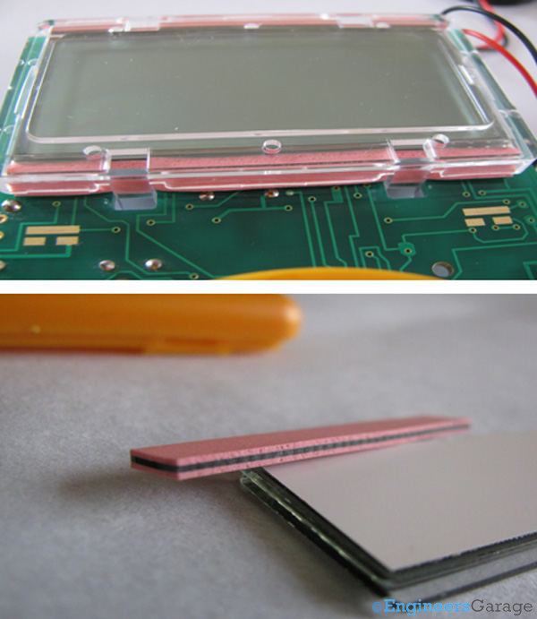
Figure 20. The plastic covering of an LCD (top) and its shock-absorption rubber pads.
The LCD is embedded on the PCB and connected through pin-outs on the board. A transparent plastic casing covers the LCD, protecting it from scratches. Rubber pads are also positioned at the LCD’s top and bottom to provide shock absorption.
How it works
After switching on the instrument, the user rotates the knob to select the desired measurement function and range. Based on this selection, specific concentric rings on the PCB are shorted, activating the corresponding section of the circuit responsible for measurements within that range. Since this is a digital measuring instrument, an Analog-to-Digital Converter (ADC) is used to convert the measured values into discrete digital readings.

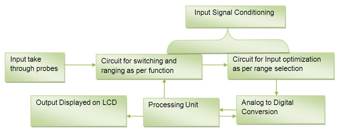
Figure 21. The block diagram of how a multimeter functions.
Except for current, most measurements in a multimeter are based on voltage. For instance, when measuring resistance, a small current is applied across the terminals of the device under test (DuT). The resulting voltage drop is then used as an input, and the internal circuitry calculates the resistance by dividing this voltage by the applied current.
The block diagram above provides an overview of the multimeter’s working principle. The input signal, taken through the probes, is initially analog, entering the internal circuitry as a wave. The first step in processing is signal conditioning, after which it is directed to the appropriate measurement circuitry. The signal is optimized based on range selection before being sent to an analog-to-digital converter (ADC). The type of ADC used varies depending on the multimeter’s capabilities and manufacturer specifications.
To convert the signal, the ADC samples the analog wave, with the sampling rate needing to be at least twice the frequency of the analog signal to ensure proper reconstruction. Most ADCs in multimeters operate using the dual-slope integration method, where the digital signal is compared to a reference. The output is processed by a successive approximation register (SAR), which sends the final data to the processing unit and balances the reference signal for optimized comparison. A clock input, provided by a crystal oscillator, is required for the SAR counter. In most multimeters, processing is limited to summing pulses within an integrator circuit.
After analog-to-digital conversion, the processed signal is sent to the processing unit, which decodes its magnitude and sends the final reading to the LCD.
Multimeters have long been an essential tool for electronic measurements and are expected to continue evolving with more advanced capabilities. While analog multimeters were once the standard, they required frequent calibration and were prone to human error. Digital multimeters, on the other hand, provide more accurate readings with higher resolution. Beyond voltage and current, modern digital multimeters can now measure temperature, capacitance, and more, with some models featuring RS232 connectors for communication with smart devices.
As technology advances, manufacturers integrate additional functionality into compact multimeter designs while maintaining efficiency and cost-effectiveness.
Filed Under: Insight
Questions related to this article?
👉Ask and discuss on EDAboard.com and Electro-Tech-Online.com forums.
Tell Us What You Think!!
You must be logged in to post a comment.