Engineers Garage

  • Projects and Tutorials
    • Electronic Projects
      • 8051
      • Arduino
      • ARM
      • AVR
      • PIC
      • Raspberry pi
      • STM32
    • Tutorials
    • Circuit Design
    • Project Videos
    • Components
  • Articles
    • Tech Articles
    • Insight
    • Invention Stories
    • How to
    • What Is
  • News
    • Electronic Products News
    • DIY Reviews
    • Guest Post
  • Forums
    • EDABoard.com
    • Electro-Tech-Online
    • EG Forum Archive
  • Digi-Key Store
    • Cables, Wires
    • Connectors, Interconnect
    • Discrete
    • Electromechanical
    • Embedded Computers
    • Enclosures, Hardware, Office
    • Integrated Circuits (ICs)
    • Isolators
    • LED/Optoelectronics
    • Passive
    • Power, Circuit Protection
    • Programmers
    • RF, Wireless
    • Semiconductors
    • Sensors, Transducers
    • Test Products
    • Tools
  • EE Resources
    • DesignFast
    • LEAP Awards
    • Oscilloscope Product Finder
    • White Papers
    • Webinars
  • EE Learning Center
    • Design Guides
      • WiFi & the IOT Design Guide
      • Microcontrollers Design Guide
      • State of the Art Inductors Design Guide
  • Women in Engineering

Insight – How Digital Thermometer works

By Ashutosh Bhatt


Digital Thermometers are slowly replacing the conventional mercury thermometer due to the ease of taking reading. People often have the misconception that it contains mercury. Digital Thermometers are mercury free. These thermometers contain thermistor inside the tip which is used to measure the temperature. They provide quick and highly accurate results over the body temperature range.

These thermometers are easy to read with LCD display on them. They are equipped with beep alarm & memory function and can record a wide range of temperature. Doctor’s thermometer which are mostly used can read temperature between 94oF and 105oF (35oC and 42oC). It is three in one thermometer as it can record oral, auxiliary and rectal temperatures.
 
Digital Thermometer
 
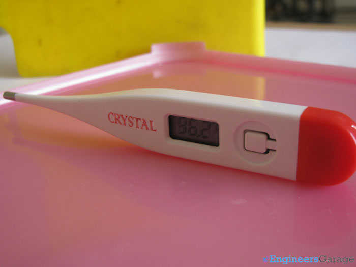
Fig. 1: Image of Digital Thermometer
 
Digital Thermometer
 
Fig. 2: Top of Thermometer having Cap that Protects Battery
 
Cap is found at the top of the thermometer, since this part is held away from the body. It is of bright colour and made up of smooth, hard plastic. The main function of this cap is to protect the battery from the outer environmental conditions.

Battery

Button Cell of Digital Thermometer
 
Fig. 3: Button Cell of Digital Thermometer
 
The battery is made up of metal and it is small and silver in colour. The type of the battery used to power the thermometer is called button cell. In technical language it is known as LR41 battery. It supplies a voltage of 1.5V under normal operating conditions. It has excellent resistance to leakage and can be stored for a long period of time. It is placed in the compartment at the back of the body under the cap.

Structure

Button Cell of Digital Thermometer

Fig. 4: Outer Body and Internal set up of Digital Thermometer

 
The body of the thermometer is made up of the slightly hard plastic as compared to cap. It measures 100.5mm long and the width increases from bottom to the top. The widest part is near the cap and the thinnest part is near the tip. It houses the display screen, electronic circuitry, power button and other parts. The design specifications vary from manufacturing company to company.
 
Button Cell of Digital Thermometer
 
Fig. 5: Image Indicating the Push Button Positioned Inside the Digital Thermometer
 
The push button is used to switch on and off the thermometer. As the button is pressed to start it, a beep signal sounds just for a second to shown that it has turned ON.
 
LCD Display of Digital Thermometer
 
Fig. 6: LCD Display of Digital Thermometer
 
The display screen also known as a LCD (Liquid Crystal Display) screen, is rectangular in shape. Normally used screen measures 15.5mm long and 6.5mm wide. The main function of the display screen is to display the temperature measurement in oC or oF. It will first display the last measured reading for 3 seconds and then start flashing. This flashing degree indicates that it is ready to measure the temperature. 

Internal Circuitry

Digital Thermometer
 
Fig. 7: Circuit Arrangement of Digital Thermometer
 
The circuit of Digital Thermometer is shown in the above image. It is made up of Microcontroller, memory which is embedded in the form of COB IC along with some passive components like capacitor, resistors, sensors, buzzer and switch. The analog value of temperature measured is converted to the digital form by Microcontroller and then displayed on the LCD. If the value of temperature exceeds the highest value then the buzzer makes a sound.

 Working

(upper image) Tip of Digital Thermometer (lower image) Close view of Thermometer Tip
 
Fig. 8: (upper image) Tip of Digital Thermometer (lower image) Close view of Thermometer Tip
 
The tip is said as the heart of the thermometer. It is the placed closed to the body part to measure the temperature of the body. The tip of the Thermometer contains thermistor to measure temperature. It is a ceramic semiconductor which is bonded in the tip with temperature sensitive epoxy. It is covered with a cap so to prevent it from the outer world. The cap may be made up of metal or stainless steel. Thermistor is responsible for converting the physical temperature into electrical signals.
 
Epoxy Coating that Contains Thermistor
 
Fig. 9: Epoxy Coating that Contains Thermistor
  
The above image shows the epoxy coating which contains the thermistor. The wires coming out are visible in the image. The temperature reading in the form of electrical signals is carried via these wires for further processing by the circuitry. Thermistor is a special kind of semiconductor in which the value of resistance changes with the change in temperature. Due to change in resistance value, the output voltage changes and the temperature change is detected.


Filed Under: Insight
Tagged With: battery, digital thermometer, temperature, thermometer
 

Questions related to this article?
👉Ask and discuss on Electro-Tech-Online.com and EDAboard.com forums.


Tell Us What You Think!! Cancel reply

You must be logged in to post a comment.

HAVE A QUESTION?

Have a technical question about an article or other engineering questions? Check out our engineering forums EDABoard.com and Electro-Tech-Online.com where you can get those questions asked and answered by your peers!


Featured Tutorials

  • Introduction to Brain Waves & its Types (Part 1/13)
  • Understanding NeuroSky EEG Chip in Detail (Part 2/13)
  • Performing Experiments with Brainwaves (Part 3/13)
  • Amplification of EEG Signal and Interfacing with Arduino (Part 4/13)
  • Controlling Led brightness using Meditation and attention level (Part 5/13)
  • Control Motor’s Speed using Meditation and Attention Level of Brain (Part 6/13)

Stay Up To Date

Newsletter Signup

Sign up and receive our weekly newsletter for latest Tech articles, Electronics Projects, Tutorial series and other insightful tech content.

EE Training Center Classrooms

EE Classrooms

Recent Articles

  • What is a loop calibrator? 
  • What are the battery-selection criteria for low-power design?
  • Key factors to optimize power consumption in an embedded device
  • EdgeLock A5000 Secure Authenticator
  • How to interface a DS18B20 temperature sensor with MicroPython’s Onewire driver

Most Popular

5G 555 timer circuit 8051 ai Arduino atmega16 automotive avr bluetooth dc motor display Electronic Part Electronic Parts Fujitsu ic infineontechnologies integratedcircuit Intel IoT ir lcd led maximintegratedproducts microchip microchiptechnology Microchip Technology microcontroller microcontrollers mosfet motor powermanagement Raspberry Pi remote renesaselectronics renesaselectronicscorporation Research samsung semiconductor sensor software STMicroelectronics switch Technology vishayintertechnology wireless

RSS EDABOARD.com Discussions

  • Passive Harmonics Filter
  • file edit
  • RCF Subwoofer Amplifier PIC16F870-I/SP please help me about hex code
  • Active Balun Design
  • What was before microcontrollers ?

RSS Electro-Tech-Online.com Discussions

  • Control Bare LCD With ATmega328p
  • Need a ducted soldering fan for solder smoke extraction
  • Identify a circuit.
  • Sla ir li ion
  • Question about ultrasonic mist maker
Engineers Garage
  • Analog IC TIps
  • Connector Tips
  • DesignFast
  • EDABoard Forums
  • EE World Online
  • Electro-Tech-Online Forums
  • Microcontroller Tips
  • Power Electronic Tips
  • Sensor Tips
  • Test and Measurement Tips
  • 5G Technology World
  • About Us
  • Contact Us
  • Advertise

Copyright © 2022 WTWH Media LLC. All Rights Reserved. The material on this site may not be reproduced, distributed, transmitted, cached or otherwise used, except with the prior written permission of WTWH Media
Privacy Policy | Advertising | About Us

Search Engineers Garage

  • Projects and Tutorials
    • Electronic Projects
      • 8051
      • Arduino
      • ARM
      • AVR
      • PIC
      • Raspberry pi
      • STM32
    • Tutorials
    • Circuit Design
    • Project Videos
    • Components
  • Articles
    • Tech Articles
    • Insight
    • Invention Stories
    • How to
    • What Is
  • News
    • Electronic Products News
    • DIY Reviews
    • Guest Post
  • Forums
    • EDABoard.com
    • Electro-Tech-Online
    • EG Forum Archive
  • Digi-Key Store
    • Cables, Wires
    • Connectors, Interconnect
    • Discrete
    • Electromechanical
    • Embedded Computers
    • Enclosures, Hardware, Office
    • Integrated Circuits (ICs)
    • Isolators
    • LED/Optoelectronics
    • Passive
    • Power, Circuit Protection
    • Programmers
    • RF, Wireless
    • Semiconductors
    • Sensors, Transducers
    • Test Products
    • Tools
  • EE Resources
    • DesignFast
    • LEAP Awards
    • Oscilloscope Product Finder
    • White Papers
    • Webinars
  • EE Learning Center
    • Design Guides
      • WiFi & the IOT Design Guide
      • Microcontrollers Design Guide
      • State of the Art Inductors Design Guide
  • Women in Engineering