Engineers Garage

  • Projects and Tutorials
    • Electronic Projects
      • 8051
      • Arduino
      • ARM
      • AVR
      • PIC
      • Raspberry pi
      • STM32
    • Tutorials
    • Circuit Design
    • Project Videos
    • Components
  • Articles
    • Tech Articles
    • Insight
    • Invention Stories
    • How to
    • What Is
  • News
    • Electronic Products News
    • DIY Reviews
    • Guest Post
  • Forums
    • EDABoard.com
    • Electro-Tech-Online
    • EG Forum Archive
  • Digi-Key Store
    • Cables, Wires
    • Connectors, Interconnect
    • Discrete
    • Electromechanical
    • Embedded Computers
    • Enclosures, Hardware, Office
    • Integrated Circuits (ICs)
    • Isolators
    • LED/Optoelectronics
    • Passive
    • Power, Circuit Protection
    • Programmers
    • RF, Wireless
    • Semiconductors
    • Sensors, Transducers
    • Test Products
    • Tools
  • EE Resources
    • DesignFast
    • LEAP Awards
    • Oscilloscope Product Finder
    • White Papers
    • Webinars
  • EE Learning Center
  • Women in Engineering

Insight – How Ding Dong Doorbell works

By Ashutosh Bhatt


The ding dong sound of the doorbells signifies the presence of someone at the door. Although there are many doorbells available in the markets today with a variety of sounds, the ding dong doorbell still has its share of the market. What makes them interesting is how do they produce this ding dong sound?

Image of Ding-Dong Bell

Fig. 1: Image of Ding-Dong Bell

The ding dong doorbells are available in many shape, sizes and colors. However the operating principles remain the same. They use the magnetic force produced by an AC solenoid to force an iron rod (called the plunger) to hit against aluminum sheets placed at both sides of the solenoid. This in turn produces the ding dong sound.
The DC and AC solenoids are different. The doorbell uses an AC solenoid. When current flows thorough the coil of an AC solenoid, a magnetic field is produced. This magnetic field produces a magnetic force and pulls the plunger in its direction. Now since the current which is flowing is AC in nature hence the magnetic force produced also reverses its direction with the frequency of AC which is 50Hz or 60Hz. As a result the plunger moves to and fro i.e. either towards the front plate or towards the back plate. When it hits the front plate it produces the ding sound and when it hits the back plate it produces the dong sound.

Arrangement of Components
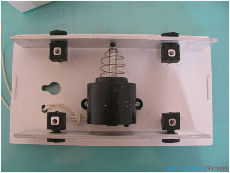
Internal Arrangement of Bell Mechanism

Fig. 2: Internal Arrangement of Bell Mechanism

The above image shows the internal arrangement of the different component of a doorbell. The various components are solenoid, spring, plunger, aluminum sheets, rubber pads, shading coil and the connecting wire.
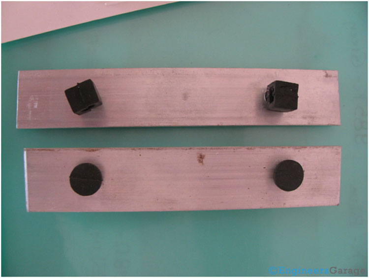
Arrangement-Rubber-Hooks-Aluminium-Sheets

Fig. 3: Arrangement of Rubber Hooks and Aluminium Sheets

The two aluminum sheets placed on either side of the solenoid. Rubber hooks are used to position them perpendicular to the plastic casing. Also this rubber hooks works as shock absorbers when the plunger hits the plates.

 Producing the Sound
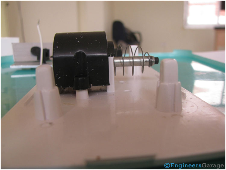
 AC Solenoid Screwed to Bell Casing

Fig. 4: AC Solenoid Screwed to Bell Casing

The above image shows the AC solenoid. It is screwed to the casing of the bell. In the default position the plunger almost touches the back aluminum plate which produces the dong sound. One end of the spring is tightly tied to the plunger and the other end is fixed in a mechanical fixture.
 
Mechanics of Ding Dong Sound System
 
Fig. 5: Mechanics of Ding Dong Sound System
 
The plunger makes the to and fro movement inside the core of the solenoid. When the button of the doorbell is pressed it hits the front plate to produce the ding sound and then comes back to hit the back plate thereby producing the dong sound.

Plunger, Spring & Solenoid

Solenoid Structure and Parts

Fig. 6: Solenoid Structure and Parts

The solenoid is made by winding an insulated copper coil on a bobbin. On the top of the coil is the sheet of paper to protect the coil windings. 

Closer look of Plunger, Spring, and Solenoid

Fig. 7: Closer look of Plunger, Spring, and Solenoid

A closer look at the plunger, spring and the solenoid. The two end of the coils are connected to the supply by means of wire as shown in the image.
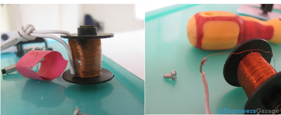
 (Left image) Insulated Copper Coil (Right image) Connection of Copper Coil with Wire
 
Fig. 8: (Left image) Insulated Copper Coil (Right image) Connection of Copper Coil with Wire
 
The above image shows the insulated copper coil used for winding and its connection with the wire to supply AC.

Shading Coil
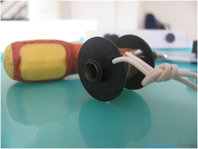
Shading Coil and Wire Arrangement

Fig. 9: Shading Coil and Wire Arrangement

The above image shows the shading coil. It is a cylindrical shaped ring, placed slightly unequally in the core of the solenoid. It is slightly coming out at one end and equally inside at the other end.
Shading coil plays an important role in the functioning of the doorbell. Since AC is sinusoidal in nature it reaches a value of zero twice in a cycle. This means the magnetic force will also be zero twice in every cycle and hence it will cause unwanted vibration and chattering.
A shading coil, which is made up of copper ring produces its own magnetic field. Now there are two magnetic fields one by the main coil and the other by the shading coil. The unequal placing of the shading coil produces unequal magnetic fields near the poles thereby producing a phase difference and avoiding the net resultant field to be zero. This in turn prevents the unwanted vibrations or chattering of the plunger.

Filed Under: Insight
Tagged With: coil, ding dong doorbell, doorbell, shading coil
 

Questions related to this article?
👉Ask and discuss on EDAboard.com and Electro-Tech-Online.com forums.


Tell Us What You Think!! Cancel reply

You must be logged in to post a comment.

HAVE A QUESTION?

Have a technical question about an article or other engineering questions? Check out our engineering forums EDABoard.com and Electro-Tech-Online.com where you can get those questions asked and answered by your peers!


Featured Tutorials

  • Designing Gate Driver Circuit and Switching Mechanism for Modified Sine Wave Inverter – (Part 9/17)
  • Completing Modified Sine Wave Inverter Design with Full Bridge Circuit and Step Up Transformer – (Part 10/17)
  • Designing an Offline UPS – Part (12 /17)
  • How to reduce Switching Time of a Relay – (Part 15/17)
  • Testing MOSFET – (Part 16/17)
  • Driving High Side MOSFET using Bootstrap Circuitry – (Part 17/17)

Stay Up To Date

Newsletter Signup

Sign up and receive our weekly newsletter for latest Tech articles, Electronics Projects, Tutorial series and other insightful tech content.

EE Training Center Classrooms

EE Classrooms

Recent Articles

  • Infineon offers DC-DC controller for full LED headlamps without a microcontroller
  • Vishay launches new high-precision, thin-film wraparound chip resistor
  • STMicroelectronics’ common-mode filters ensure signal integrity in serial interfaces
  • Renesas’ RA Family microcontrollers earn CAVP certification for cryptographic algorithms
  • MicroPython: Serial data communication in ESP8266 and ESP32 using UART

Most Popular

5G 555 timer circuit 8051 ai Arduino atmega16 automotive avr dc motor display Electronic Part Electronic Parts Fujitsu ic infineontechnologies integratedcircuit Intel IoT ir lcd ldr led maximintegratedproducts microchip microchiptechnology Microchip Technology microcontroller microcontrollers mosfet motor powermanagement Raspberry Pi remote renesaselectronics Research robot samsung semiconductor sensor software STMicroelectronics switch Technology vishayintertechnology wireless

RSS EDABOARD.com Discussions

  • PS4 chip replacement not going to plan
  • Level shifter for differential oscillator
  • Voltage reference level - how to choose?
  • Boost converter, 3W...shielded or unshielded inductor?
  • What is the function of the long stub?

RSS Electro-Tech-Online.com Discussions

  • SPI Questions
  • Dog Scarer
  • Unusual phenomenon
  • Audio equalizer
  • Background of Members Here
Engineers Garage
  • Analog IC TIps
  • Connector Tips
  • DesignFast
  • EDABoard Forums
  • EE World Online
  • Electro-Tech-Online Forums
  • Microcontroller Tips
  • Power Electronic Tips
  • Sensor Tips
  • Test and Measurement Tips
  • 5G Technology World
  • About Us
  • Contact Us
  • Advertise

Copyright © 2022 WTWH Media LLC. All Rights Reserved. The material on this site may not be reproduced, distributed, transmitted, cached or otherwise used, except with the prior written permission of WTWH Media
Privacy Policy | Advertising | About Us

Search Engineers Garage

  • Projects and Tutorials
    • Electronic Projects
      • 8051
      • Arduino
      • ARM
      • AVR
      • PIC
      • Raspberry pi
      • STM32
    • Tutorials
    • Circuit Design
    • Project Videos
    • Components
  • Articles
    • Tech Articles
    • Insight
    • Invention Stories
    • How to
    • What Is
  • News
    • Electronic Products News
    • DIY Reviews
    • Guest Post
  • Forums
    • EDABoard.com
    • Electro-Tech-Online
    • EG Forum Archive
  • Digi-Key Store
    • Cables, Wires
    • Connectors, Interconnect
    • Discrete
    • Electromechanical
    • Embedded Computers
    • Enclosures, Hardware, Office
    • Integrated Circuits (ICs)
    • Isolators
    • LED/Optoelectronics
    • Passive
    • Power, Circuit Protection
    • Programmers
    • RF, Wireless
    • Semiconductors
    • Sensors, Transducers
    • Test Products
    • Tools
  • EE Resources
    • DesignFast
    • LEAP Awards
    • Oscilloscope Product Finder
    • White Papers
    • Webinars
  • EE Learning Center
  • Women in Engineering