Testers are one of the simplest solutions, used to test current and voltage continuity in any circuit. Indispensible for any electrician, the testers are very simple and interesting devices. This article will explore the internal structure of one such commonly used circuit tester.
The user is required to be on the floor while using the tester so that he can serve as ground when current flows. In order to test the live wire, the user’s body must be in contact with the metal cap on the top of the screwdriver when the tester is put in contact with the wire. This completes a genuine electrical circuit and the bulb will light up once the tester senses voltage.
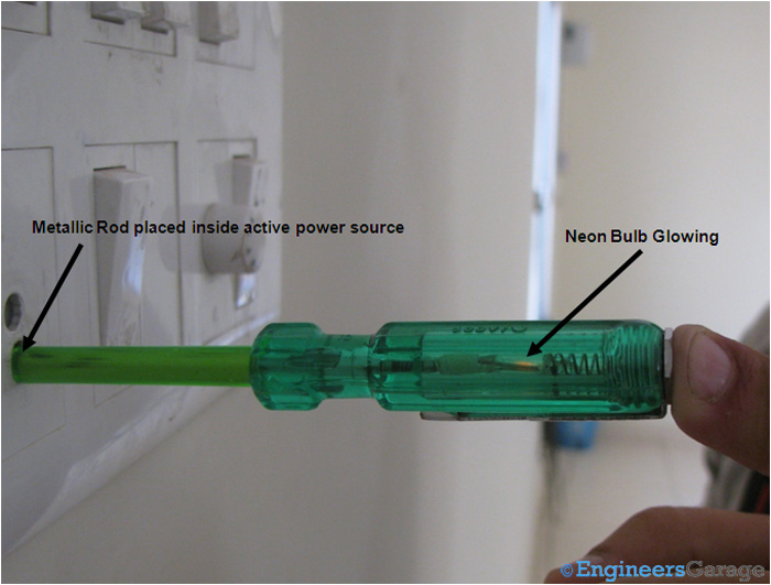
Fig. 1: Tester Set Up
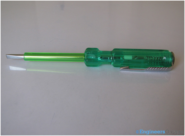
Fig. 2: Screwdriver Cum Tester
The tester shown above is a screwdriver cum testing circuit. The core of the tester is located near the head of the screwdriver. The plastic casing under which the tester circuitry is placed serves as an insulator. As the metallic rod is the conductor part of the tester, in order to protect the user from getting an accidental electric shock, a thick sheath of plastic insulator is placed over metallic rod
Structure

Fig. 3: Metallic Cap at Screwdriver Top to Hold Circuit
A threaded metallic cap is at the top of the screwdriver holding the circuit inside. The cap needs to be grounded when the metallic rod is inserted in the plug. The power socket is analogous to the positive terminal of a battery. Just like in the case of a battery we need to connect the other end of the circuit to the negative terminal where the current sinks in, we need a sink for the current from the power source too. The ground acts as that sink in this case. Most of the time, the user forms the link to ground for the circuit which is created when rod is inserted in the power source. The user does not get any kind of shock because there is already current limiting resistors in the testers and also because a dry human body has very large electrical resistance.
Neon Bulb Assembly
The cap is followed by a spring. The spring has a dual functionality of acting as an earth wire and connecting the tester circuitry to the cap when screwdriver is placed inside a socket.
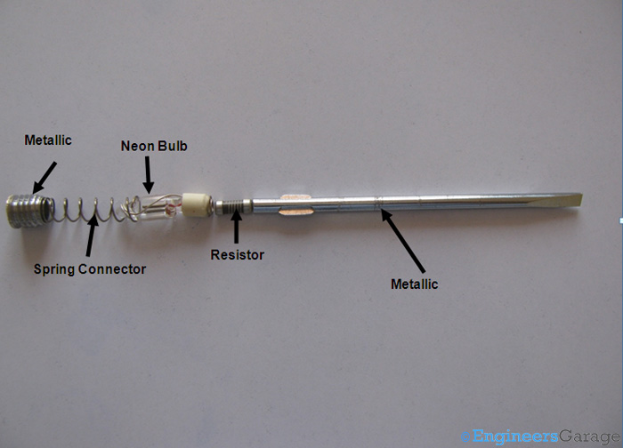
Fig. 4: Screwdriver Circiut Set Up
After the plastic insulating sheath is removed, the circuitry of the screwdriver can be seen clearly as shown above.
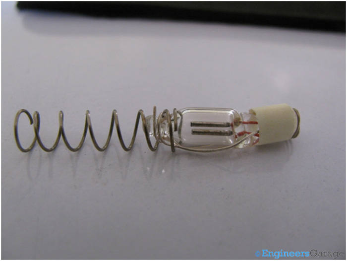
Fig. 5: Neon Bulb–Spring Wire Connection
The above image shows the neon bulb connected to the spring through a wire. It serves as an indicator of current whenever the metallic rod is plugged inside an active power source. The neon bulb gives output instantaneously and doesn’t get heated due to high voltage. The current requirement of the bulb is quite low and acts quite satisfactorily when circuit is grounded with the help of human body.

Fig. 6: Resistor to Connect Neon Bulb with Metallic Rod
A resistor like one shown in the picture above is connected to the neon bulb from one end and to the metallic rod from the other. The maximum current from the power source that can travel to the neon bulb is limited by the resistor.
Metallic Rod
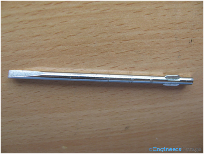
Fig. 7: Metallic Rod Cum Screwdriver
The metallic rod is placed on the line upon which voltage has to be tested. Additionally, it serves the purpose of a screwdriver for general purpose use. In this way a very simple electrical circuit is used for debugging circuit breaks and tests their continuity.
Filed Under: Insight


Questions related to this article?
👉Ask and discuss on EDAboard.com and Electro-Tech-Online.com forums.
Tell Us What You Think!!
You must be logged in to post a comment.