Electronic ballasts are gradually replacing conventional magnetic ballasts (commonly known as choke) from the fluorescent tubes. They have higher efficiency as compared to magnetic ballasts and provide a flicker free start up to the tube. Also it does not produce the ‘hum’ sound which is very annoying with the magnetic ballast. There are two primary functions of the electronic ballast:
1. To provide the initial high voltage required to ionize the gas, thereby setting up an arc between the two electrodes.
2. To limit the current through the tube once it has started up. If the current is not controlled it may result in voltage spike thereby damaging the lamp.
The other functions include ignition, warm-up, constant power control, power factor correction, and protection against all lamp and ballast fault conditions.
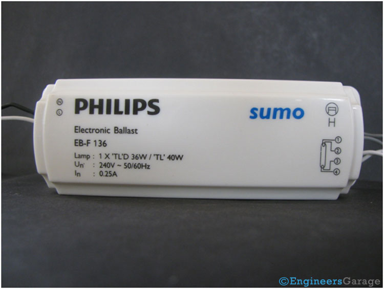
Fig. 1: Image Showing A Typical Electronic Ballast
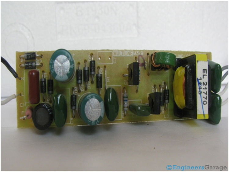
Fig. 2: Electronic Ballast’s Printed Circuit Board
Electronic Ballast Components

Fig. 3: Electronic Components of Ballast’s PCB

Fig. 4: Electronic Ballast PCB Capacitors
Rectifier & Inverter
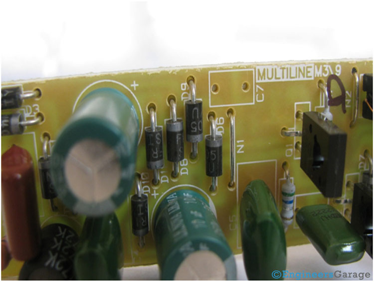
Fig. 5: Image Showing Positioning of Diodes In An Electronic Ballast
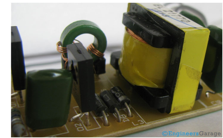
Fig. 6: Closer Look At Inverter In Electronic Ballast’s PCB
Use of Transformer
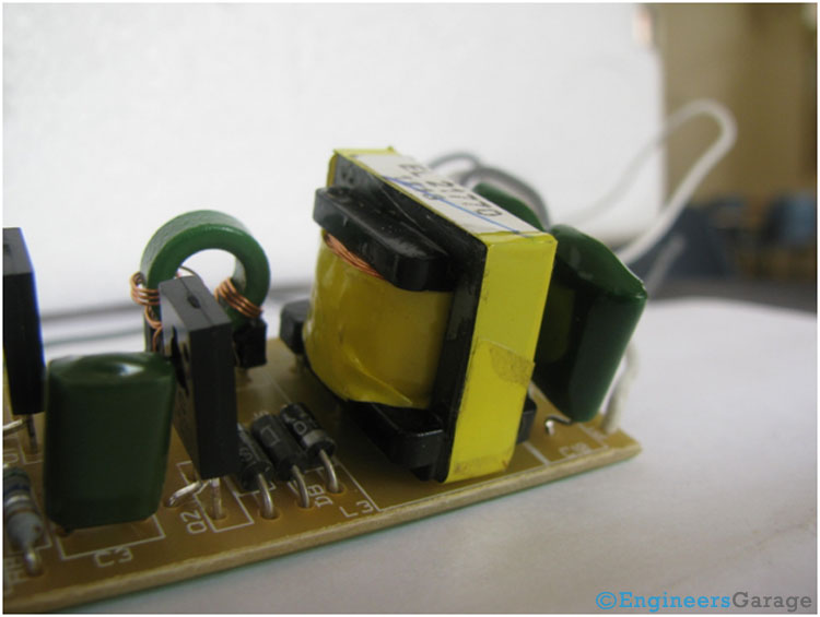
Fig. 7: Image Showing Positioning of A Transformer In PCB Circuit of Ballast
Filed Under: Insight


Questions related to this article?
👉Ask and discuss on EDAboard.com and Electro-Tech-Online.com forums.
Tell Us What You Think!!
You must be logged in to post a comment.