Every big fire starts as a little spark.
“Spark”, has been the first step of mankind towards progress and prosperity. Spark from the stones that created the first fire; fire gave ability to mould and soften things. Even today, one needs a little spark to set things off, from firing furnaces for extraction of metals to sending an airship to the space, to cooking our supper. Without a spark there would be no fire, and without a fire, fuel would not burn. If fuel would not burn, then energy would not be released, and if there is no energy release, most things of the today’s world would come to a screeching halt.
One such device that ignites fuel in our day to day activities, especially in the kitchen, is the electric lighter. Now, most kitchens depending on LPG are already equipped with a piezoelectric lighter, so why would one want to switch over to an electric variant? Why use something that runs on batteries when we have something that can run without it? Electronic gas lighters are relatively lighter and have replaceable batteries. So, they don’t die out when the power source dies like in the case of piezoelectric lighters, just change the batteries and we are good to go again. What kinds of batteries are used in such a lighter? What circuitry does such a lighter has so that only a single battery is able to generate such electric sparks? What is the magnitude of voltage in the spark so produced? Are these lighters repairable? Let’s find out this, and much more about the electric lighter.

Fig. 1: Image of Electronic Gas Lighter
Outer Casing

Fig. 2: Outer Assembly—Push Button, Battery Cover, Body Cover
The outer casing of the lighter is a light weight plastic assembly comprising of a push button, body enclosing the circuit of the lighter and the battery cover. The length of the lighter is intentionally kept longer so as to avoid the user from getting hurt from the spark.
The lower part of the lighter is metallic as it serves as an electrode for spark conduction. When the voltage is discharged from the spark generator, it needs a cathode (destination) that generates a potential gradient so that spark can be produced.

Fig. 3: Spark Generation Part of Lighter
The image above shows the spark generation and the manner in which it reaches the electrode. The point of spark generation is not fixed. There are sections cut on the metal part so that the air-gas mixture that is created when the gas stove is turned on, can come in contact with the spark and ignite.
PCB
PCB: Components and Flexible Switch

Fig. 4: Internal Circuitry of Electronic Lighter
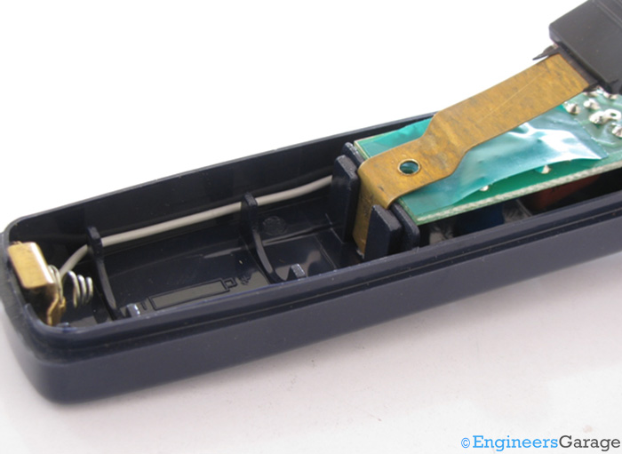
When the top part of the plastic casing is removed, the internal circuitry of the lighter is visible. It consists of a slot for battery, a flexible push switch which looks like miniature diving board, a PCB, connecting wires and an ignition coil. While the circuitry remains more or less the same for every manufacturer, battery slots can vary. To prevent the switch from making contact with the components of the PCB, a thin insulation tape sticks to the surface of the PCB. Shown in the image above is a slot for AA battery. Other popular types of batteries used are AAA and a USB rechargeable battery. The minimum voltage required by a battery is 1.5 volt, thus allowing user to install batteries that are easily available.

Fig. 5: Closer View of Battery Slot Showing the Connection System of Battery and Push Switch
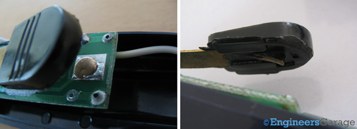
The positive end of the battery is connected to the flexible push switch while the negative end acts as body ground. To complete the current flow through the battery, the flexible switch connects to a metallic plate embedded on the PCB as shown below.

Fig. 6: Closer View of Metal Plate and Connection Mechanism with Lighter Switch
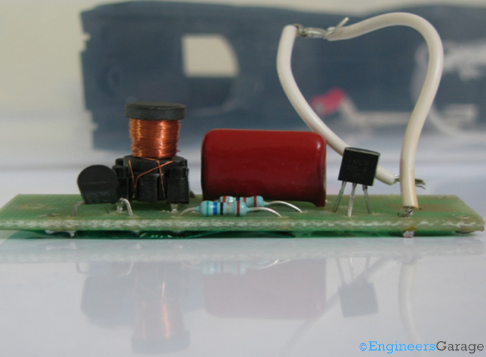
The PCB is utilized from both the sides with one side having an embedded metal plate which comes in contact with the push switch when latter is pressed, thus completing the circuit. It forms the switch of the lighter. This side also has the metal tracks which form the conduction paths across the circuit components. The other side of the PCB holds the components required for spark generation.

Fig. 7: Image Showing Circuit Components of Lighter PCB
Capacitor Discharge Ignition System

Fig. 8: Image Showing Capacitor Discharge Ignition System of Electronic Lighter
The circuit is a simple example of a capacitor discharge ignition system. The circuit diagram as on the board has been drawn in the figure below.

Fig. 9: Circuit Diagram of Ignition System
It consists of a small transformer to couple voltage from the battery circuit and step it up. The NPN transistor connected in a common base configuration acts as a voltage amplifier whose output is applied across the transformer. The battery is far from ideal and has a finite rise time in which the voltage is built up across circuit elements from 0 to the final value. This transient state links flux and induces voltage across the first transformer which is stepped up. Further, it consists of a charging circuit which has the high capacity capacitor as its central element to store energy. This stores energy in the form of electric field in contrast to inductive discharge systems, which take a lot of time to store energy as magnetic fields. Nominally, about 100-150V should be available when the circuit fires, hence the turn ratio of the first transformer is chosen accordingly. A fast recovery rectifier (diode) prevents the capacitor from discharging back into the input circuit. The triggering of the discharge is controlled by the gate current to a Silicon Controlled Rectifier (SCR), which is simply through the potential divider segment here. The choice of resistors is such that enough current is available for the Gate terminal to fire the SCR.

Fig. 10: Parts of Lighter Circuitry
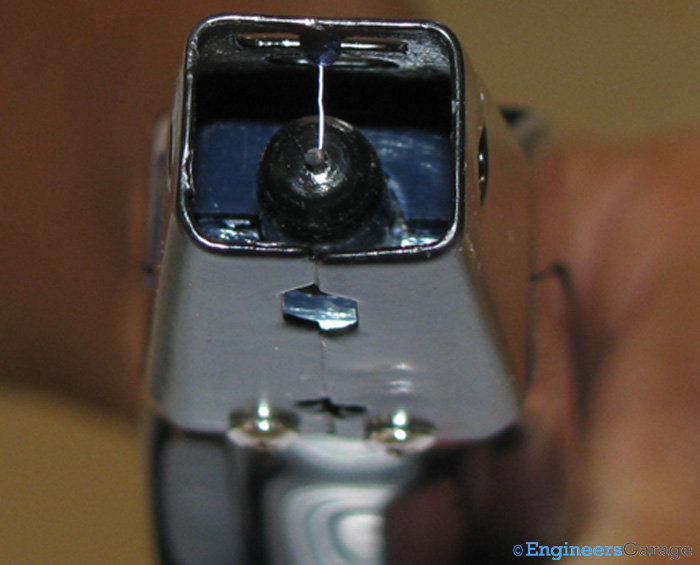
The output of the PCB circuitry is fed into a high voltage coil which is insulated with the help of a tight plastic casing. This high voltage coil is responsible for creating the spark in the lighter and is termed as ignition transformer. The ignition coil is another low inductance step up transformer with its primary windings in the triggering circuit, and the secondary windings connected to the walls across the air gap. It is termed so because it creates a spark as output. Such transformers are also used in ignition systems of vehicles. In this type of transformer, primary and secondary are wound over a single iron core. Iron is economic and can be easily magnetized. Also, since only one discharge is required in a single operation, we don’t need to be concerned about the hysteresis losses in the material used. So, iron works just fine. Primary coil is wound at the outermost part while secondary is sandwiched between the primary and the core. The ignition transformer is a step-up transformer which means that the secondary has more turns than the primary. The relativity in the number of turns is responsible for lowering or incrementing the voltage. A step up transformer increases the voltage induced across the secondary coil by increasing the number of turns, thus increasing the amount of flux linked with it. To attain voltages enough to create a spark, the number of turns in secondary is about hundred times more than the primary. One terminal of the secondary protrudes out towards the center of the air gap to form the anode for the discharge system. The other terminal of the coil is connected to a wire, which is connected to the metallic part on the mouth of the lighter to serve as the cathode as shown in the images below.

Fig. 11: Image Showing Connection Pattern

Fig. 12: Mouth of Lighter that Acts as Cathode
The electric arc formed travels from the central anode, to the peripheral cathode and the gas in between the two is raised to its ignition temperature.
Working
Whenever the switch of the lighter is pressed, it causes the flexible metallic switch to establish contact with the PCB and provides voltage to the circuit. The voltage is then amplified and stored in the capacitor. When a high voltage discharge takes place through the capacitor as current through the Gate terminal of SCR exceeds the firing current, a very high voltage is induced across the secondary terminals. This voltage (of the order of a few kilovolts) is enough to cause the electrical breakdown of the air present in the air gap and a momentary spark is produced as the circuit fires.

Fig. 13: Ignition Part of Electronic Lighter
This spark is enough to make the inflammable gas burn as a steady flame. Voltage build up lasts for a very short duration, since the source is a DC voltage source. This means, that after the initial buildup of potential, no voltage is induced with the transformer, and hence the SCR turns off until the user presses the switch again.
Filed Under: Insight


Questions related to this article?
👉Ask and discuss on EDAboard.com and Electro-Tech-Online.com forums.
Tell Us What You Think!!
You must be logged in to post a comment.