Geared DC motors can be defined as an extension of DC motor which already had its Insight details demystified here. A geared DC Motor has a gear assembly attached to the motor. The speed of motor is counted in terms of rotations of the shaft per minute and is termed as RPM .The gear assembly helps in increasing the torque and reducing the speed. Using the correct combination of gears in a gear motor, its speed can be reduced to any desirable figure. This concept where gears reduce the speed of the vehicle but increase its torque is known as gear reduction. This Insight will explore all the minor and major details that make the gear head and hence the working of geared DC motor.
External Structure
At the first sight, the external structure of a DC geared motor looks as a straight expansion over the simple DC ones.
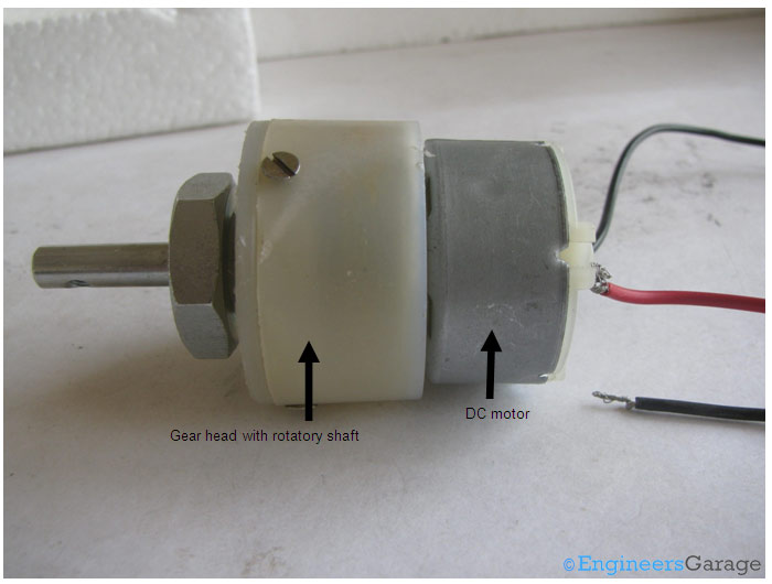
Fig. 1: External Structure of DC Geared Motor
The lateral view of the motor shows the outer protrudes of the gear head. A nut is placed near the shaft which helps in mounting the motor to the other parts of the assembly.
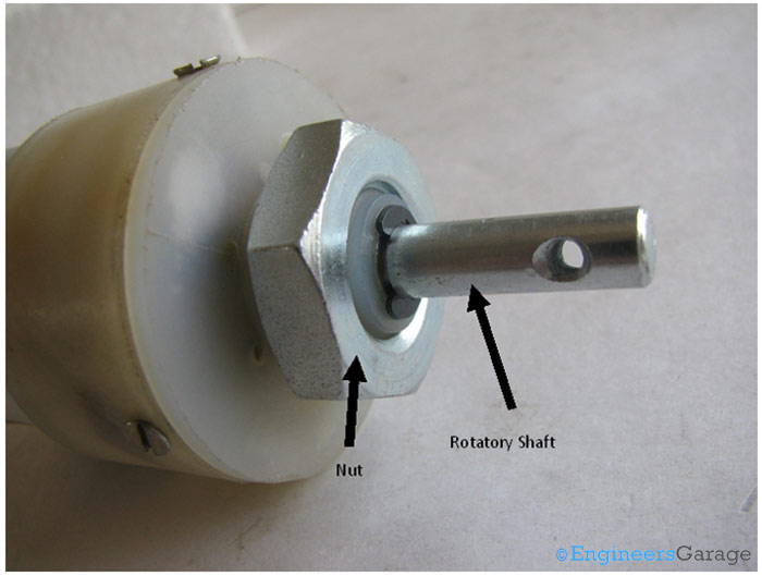
Fig. 2: Lateral View of Parts of Motor
Also, an internally threaded hole is there on the shaft to allow attachments or extensions such as wheel to be attached to the motor.
Outer Body of Gear Head & Rear View
The outer body of the gear head is made of high density plastic but it is quite easy to open as only screws are used to attach the outer and the inner structure. The major reason behind this could be to lubricate gear head from time to time.
The plastic body has a threading through which nut can be easily mounted and vice versa from the gear head.
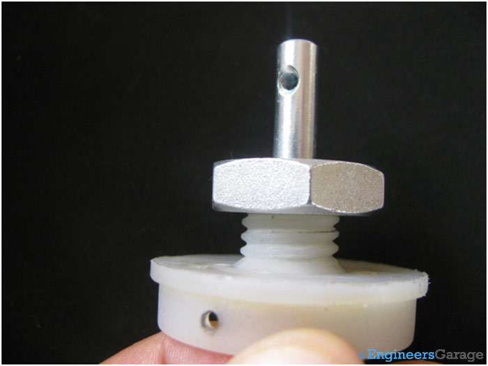
Fig. 3: Outer Structure of Gear Head
Rear View
The rear view of the geared motor is similar to the DC motor and it has two wires soldered to it.
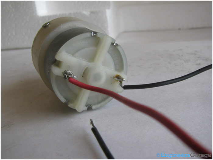
Fig. 4: Rear View of Parts of DC Motor
Internal Structure
Internal Structure
On opening the outer plastic casing of the gear head, gear assemblies on the top as well as on bottom part of the gear head are visible. These gear assemblies are highly lubricated with grease so as to avoid any sort of wear and tear due to frictional forces. Shown below is the top part of the gear head. It is connected to rotating shaft and has one gear that allows the rotation. A strong circular imprint shows the presence of the gear that rotates the gear at the upper portion.
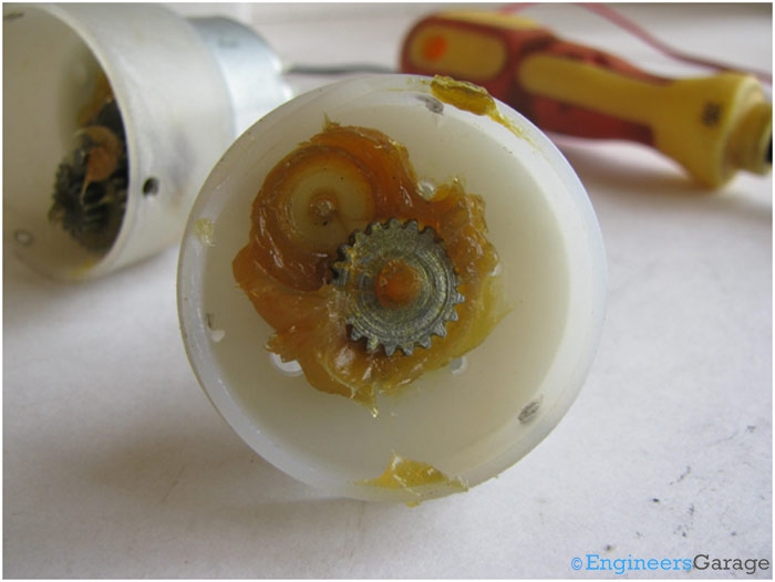
Fig. 5: Gear Assembly
Connection of the shaft with the gear is shown in the image under.
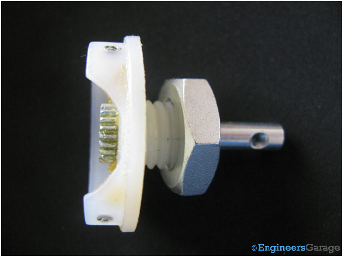
Fig. 6: Image showing Connection of Shaft with Gear
The cap that accommodates the gear has an arc cut from its side to avoid frictional resistance forces with the bottom gear assembly.
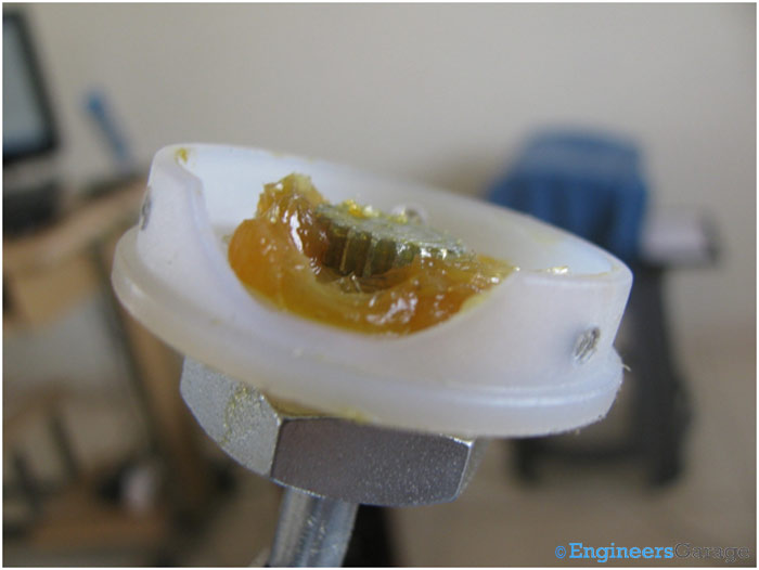
Fig. 7: Shape of Cap that Accomodates Gear
The bottom houses the gear mechanism which is connected to the DC motor through screws. This mechanism rotates the gear at the top which is connected to the rotating shaft.
Bottom Gear Assembly
A closer look at the bottom gear assembly shows the structure and connection with other gears.
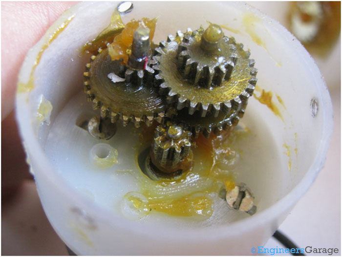
Fig. 8: Shape of Bottom Gear Assembly
Gear assembly’s association with the motor (bottom gear assembly) can be understood with the help of the image shown below.
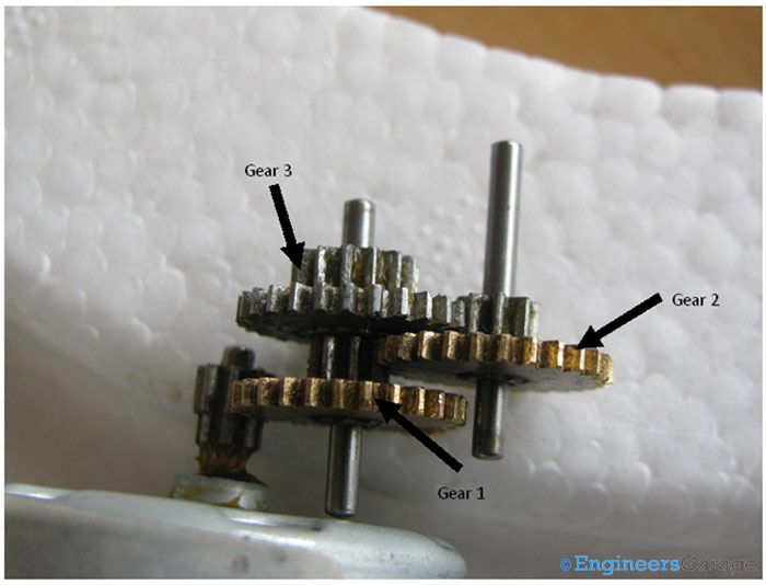
Fig. 9: Parts of Bottom Gear Assembly
The gear assembly is set up on two metallic cylinders whose working can be called as similar to that of an axle. A total of three gears combine on these two cylinders to form the bottom gear assembly out of which two gears share the same axle while one gear comes in between them and takes a separate axle.
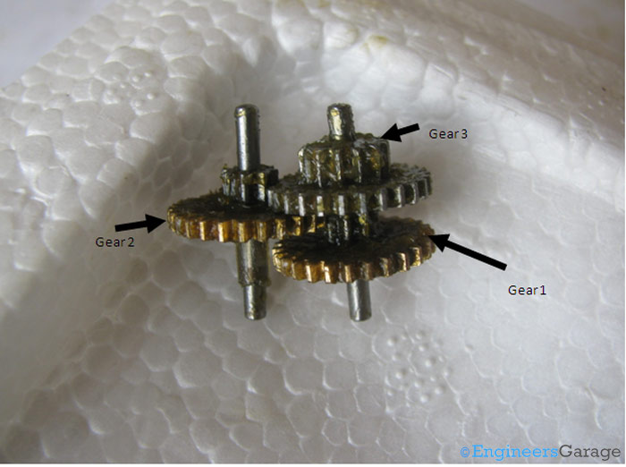
Fig. 10: Figure Indicating the Types of Gears
The gears are basically in form of a small sprocket but since they are not connected by a chain, they can be termed as duplex gears in terms of a second cog arrangement coaxially over the base. Among the three gears, two are exactly same while the third one is bigger in terms of the number of teeth at the upper layer of the duplex gear. The third gear is connected to the gear at the upper portion of the gear head. The manner in which they are located near the upper part of the gear head can be seen through the image shown below.
The combination of bottom gear assembly with the upper one can be seen down under.
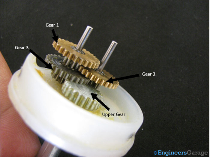
Fig. 11: Combination of Bottom Gear Assembly
Combination of Gear Assemblies
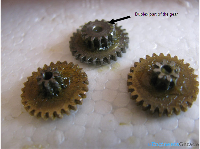
Fig. 12: Gears Shown Separately
After the gear assembly is removed, gear head’s connection to the DC motor and its gear can be easily seen. The machine has a smaller gear in comparison to the gear head’s gear assembly.
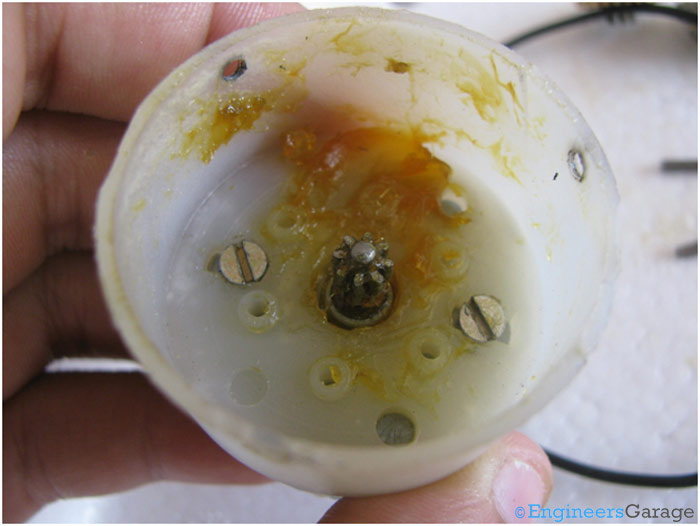
Fig. 13: Gear Head and its Parts
Working
Working of the DC Geared Motor
The DC motor works over a fair range of voltage. The higher the input voltage more is the RPM (rotations per minute) of the motor. For example, if the motor works in the range of 6-12V, it will have the least RPM at 6V and maximum at 12 V.
In terms of voltage, we can put the equation as:
RPM= K1 * V, where,
K1= induced voltage constant
V=voltage applied

Fig. 14: Functional Mechanism of Gear Assembly
The working of the gears is very interesting to know. It can be explained by the principle of conservation of angular momentum. The gear having smaller radius will cover more RPM than the one with larger radius. However, the larger gear will give more torque to the smaller gear than vice versa. The comparison of angular velocity between input gear (the one that transfers energy) to output gear gives the gear ratio. When multiple gears are connected together, conservation of energy is also followed. The direction in which the other gear rotates is always the opposite of the gear adjacent to it.
In any DC motor, RPM and torque are inversely proportional. Hence the gear having more torque will provide a lesser RPM and converse. In a geared DC motor, the concept of pulse width modulation is applied. The equations detailing the working and torque transfer of gears are shown below:
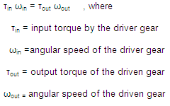
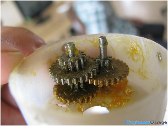
Fig. 15: Gear Assembly Placed in Gear Head
In a geared DC motor, the gear connecting the motor and the gear head is quite small, hence it transfers more speed to the larger teeth part of the gear head and makes it rotate. The larger part of the gear further turns the smaller duplex part. The small duplex part receives the torque but not the speed from its predecessor which it transfers to larger part of other gear and so on. The third gear’s duplex part has more teeth than others and hence it transfers more torque to the gear that is connected to the shaft.
Filed Under: Insight


Questions related to this article?
👉Ask and discuss on EDAboard.com and Electro-Tech-Online.com forums.
Tell Us What You Think!!
You must be logged in to post a comment.