A Lithium coin battery is a sub category of primary batteries. The name is derived from the shape which resembles a coin. Both the types – disposable and rechargeable – are available in the market in a variety of sizes. Some common applications are wristwatches, calculators, hearing aids, RTC, sensors, motherboard (to keep the time and date updated), memory units etc. The battery used in this article is disposable type. The key chemical constituents are Lithium, Manganese oxide, and an organic electrolyte. The voltage range for these types of batteries varies from 1.5V to 3.7 V.
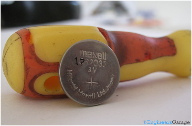
Fig. 1: Image Showing Positive Terminal of Coin-type Lithium Battery
The front view of a commonly used coin type battery is shown in the image above. The positive mark indicates the positive terminal of the battery.
Rear View/Negative Terminal
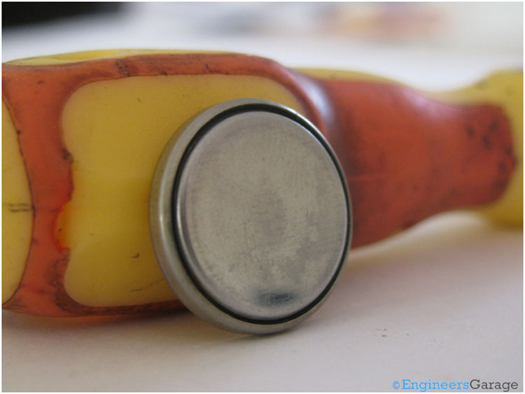
Fig. 2: Negative Terminal of Battery
The above image shows the rear view of the battery which behaves as the negative terminal of the battery. When used in a device or to power an electronic circuit the polarities should be properly taken care of else it may result in distortion, leakage, overheating, explosion or fire thereby damaging the device.
Internal Structure
Fig. 3: Internal Structure of Positive Terminal
On removing the top positive metal can, the coin cell looks as shown in the image above. Proper care should be taken in case it is required to solder wires on the top and bottom can as improper soldering may result in damage of the cell. Learn some exciting tips on soldering.
Bottom Container
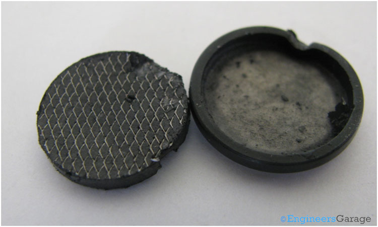
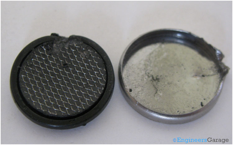
Fig. 4: Internal Structure of Bottom Metallic Container
The above image shows the bottom metallic container after removing the solid paste like mass of manganese dioxide. The walls of the bottom container are covered with a black mechanical seal called the gasket. The gasket prevents leakages of the chemical compounds in the cells to the outside environment, thereby avoiding damage to the equipments. The gasket is made up of a rubber like material with high strength to bear mechanical stresses.
Separator Arrangement

Fig. 5: Bottom Metal can Separator Arrangement
An isolation paper as shown in the image above is pasted on the bottom metal can. Below the isolation paper is the electrolyte and layer of Lithium.
Isolation Paper
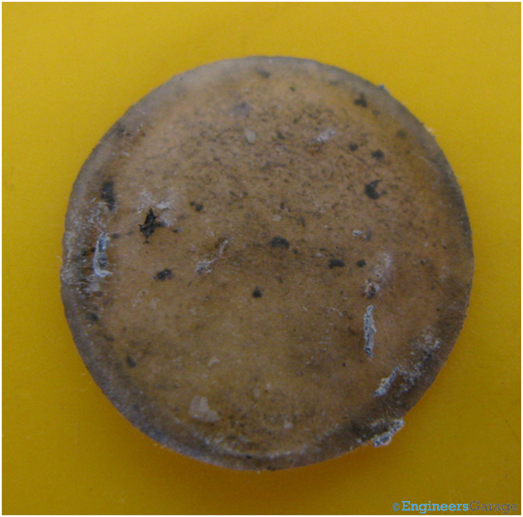
Fig. 6: Separator Paper or Isolator of Connector
A clear view of the isolator/separator paper is shown in the image above. It is made up of a porous material and allows the ions to pass through it and prevent the masses to interact with each other.
Electrolyte & Lithium layer

Fig. 7: Layer of Organic Electrolyte in Bottom Can
Beneath the separator in the bottom can is the layer of organic electrolyte in the form of paste. Below this paste is the layer of Lithium which acts as the cathode/negative electrode.
Manganese Dioxide Mass

Fig. 8: Components of Anode of Battery
The above image shows the solid mass of manganese dioxide which acts as anode/positive electrode of the battery. Manganese dioxide is in the form of a semi solid paste or gel with a metal grid at the top.
Metal Grid
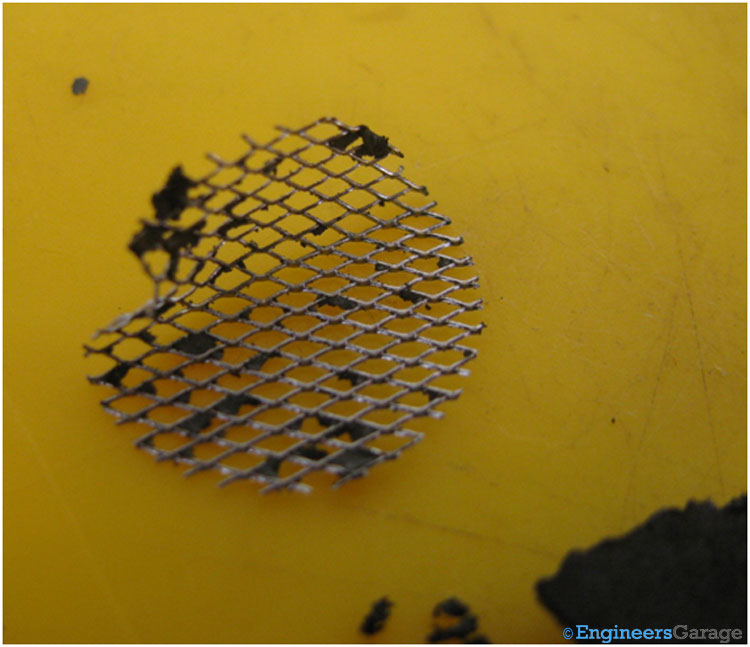
Fig. 9: Metal Grid for Anode
The metal grid which is placed at the top of the manganese dioxide serves as the current collector for the anode.
You may also like:
Filed Under: Insight




Questions related to this article?
👉Ask and discuss on Electro-Tech-Online.com and EDAboard.com forums.
Tell Us What You Think!!
You must be logged in to post a comment.