Engineers Garage

  • Electronic Projects & Tutorials
    • Electronic Projects
      • Arduino Projects
      • AVR
      • Raspberry pi
      • ESP8266
      • BeagleBone
      • 8051 Microcontroller
      • ARM
      • PIC Microcontroller
      • STM32
    • Tutorials
      • Audio Electronics
      • Battery Management
      • Brainwave
      • Electric Vehicles
      • EMI/EMC/RFI
      • Hardware Filters
      • IoT tutorials
      • Power Tutorials
      • Python
      • Sensors
      • USB
      • VHDL
    • Circuit Design
    • Project Videos
    • Components
  • Articles
    • Tech Articles
    • Insight
    • Invention Stories
    • How to
    • What Is
  • News
    • Electronic Product News
    • Business News
    • Company/Start-up News
    • DIY Reviews
    • Guest Post
  • Forums
    • EDABoard.com
    • Electro-Tech-Online
    • EG Forum Archive
  • DigiKey Store
    • Cables, Wires
    • Connectors, Interconnect
    • Discrete
    • Electromechanical
    • Embedded Computers
    • Enclosures, Hardware, Office
    • Integrated Circuits (ICs)
    • Isolators
    • LED/Optoelectronics
    • Passive
    • Power, Circuit Protection
    • Programmers
    • RF, Wireless
    • Semiconductors
    • Sensors, Transducers
    • Test Products
    • Tools
  • Learn
    • eBooks/Tech Tips
    • Design Guides
    • Learning Center
    • Tech Toolboxes
    • Webinars & Digital Events
  • Resources
    • Digital Issues
    • EE Training Days
    • LEAP Awards
    • Podcasts
    • Webinars / Digital Events
    • White Papers
    • Engineering Diversity & Inclusion
    • DesignFast
  • Guest Post Guidelines
  • Advertise
  • Subscribe

Insight – How Magnetic Ballast works

By Ashutosh Bhatt July 5, 2012


Magnetic ballast is an essential component in traditional discharge lamps and tubes. In order to properly start them, an initial high current is needed which needs to be limited afterwards to prevent the lamp from blowing out. This function is performed by ballast. Electro-magnetic ballasts were one of the first components that could provide sufficient starting current to fluorescent lights or low pressure tanning lamps. Although they are being replaced by much lighter and efficient, electronic ballasts, electro-magnetic ballasts are still in trend. This article will explore the structural features of the ballast and its working.
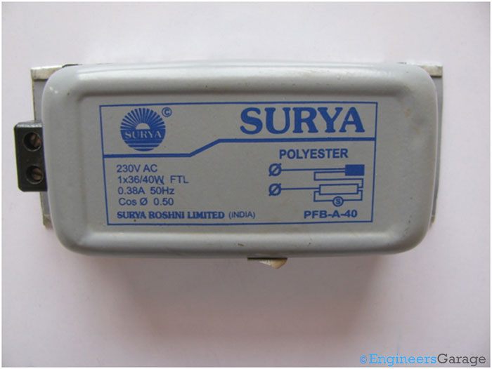
Image Showing A Typical Magnetic Ballast

Fig. 1: Image Showing A Typical Magnetic Ballast

 
Casing
Numerous manufacturers are producing their own customized versions of Magnetic ballasts. Depending upon the brands, size and the power requirements, ballasts can be of various types. Shown above is typical Magnetic ballast. The casing is made of Aluminum and has the specifications featured over it. On its side are two connecting plugs which connect the ballast to the fluorescent light.

Casing of Magnetic Ballast

Fig. 2: Casing of Magnetic Ballast
The top view and side view of the ballast suggest that there are no screws or bolts to hold the casing to the internal structure of the ballast. The casing is clamped by a steel frame at the base that aids in attaching the ballast to the lamp frame.

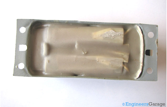
Image Showing Inside View of Magnetic Ballast Casing

Fig. 3: Image Showing Inside View of Magnetic Ballast Casing

A look at the base of the ballast after removing the steel plate reveals the answer, to what holds the frame and the internal components together? The base is firmly coated by polyester reinforced with fiber glass which helps the internal structure to hold on tight to the external aluminum frame. It is an example of potted core and coil magnetic ballast.
This potting mixture provides excellent sound deadening and transfer of heat to the aluminum frame. This decreases hum and increases efficiency of the ballast. Polyester also acts as a gasket separating the casing from the internal structure, hence providing least parasitic inductance to the ballast.

Internal Structure

Inner Structure:

Inner Structure of Magnetic Ballast

Fig. 4: Inner Structure of Magnetic Ballast

Internal structure of the ballast is also coated with fiber glass reinforced polyester resin that covered the rear portion of the ballast. The connecting plugs are tightly attached to the ballast through this resin and cardboard paper. This is done to provide high level of insulation while having lower costs. The wires emerging out of the plugs are also insulated well before they connect to the copper windings.
Etching off the resin from the surface reveals the laminated copper coils. Thorough lamination of the coils reduces the losses incurred due to eddy currents and inductance even at the high operating voltages and inductance value ratings.

Working of Magnetic Ballast

The coiled structure looks like a transformer, but is quite simpler and different from that. The coil is the main part of the whole assembly that is responsible for the ballast action. The coiling of the copper around a core material makes it an inductor. Inductors are known to oppose any change in current passing through them and this very property is used in the ballast. Let us review the main functions of the ballast once again and see how this simple inductance coil achieves them.
 

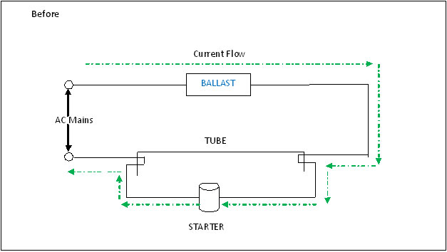
Diagrammatical Figure Showing Magnetic Ballast Structure Before Current Flow

Fig. 5: Diagrammatical Figure Showing Magnetic Ballast Structure Before Current Flow

Ballast is used to help light up fluorescent lamps. The ends of the fluorescent lamp have electrodes which need preheating to a substantially high temperature for the lamp to start. During this initial phase, the ballast opposes the setting up of current flowing through the electrodes into the starter to prevent damage. This provides the necessary current limiting.  Meanwhile voltage develops across the ballast as it goes on opposing the increase in current and keeps on storing energy. The starter in series with the ballast acts as a time switch and initially is in ON state. The current flow is as shown in the figure above. After a while, the starter goes to its OFF position and the current flow now must take place through the tube. Fluorescent lamps have low pressure gas inside them which is a bad conductor of electricity initially. So, an initial kick or a very high voltage impulse is required to strike an arc across the lamp. This kick is provided by the voltage that had developed across the ballast all the time it was opposing the increase in current.

Diagrammatical Figure Showing Magnetic Ballast Structure After Current Flow

Fig. 6: DIagrammatical Figure Showing Magnetic Ballast Structure After Current Flow

But due to passage of current through the air inside the lamp, it ionizes and its resistance to current flow decreases progressively as the current goes on increasing. If this is not checked, the lamp may get shorted and even blast. This limiting again, is provided by the ballast. The inductance coil now acts as a reactance and limits the maximum current that is allowed to pass through the circuit. The greater the inductance of the coil, the more it can limit the current. The resistance goes on increasing to a maximum value after which normal current would flow through the lamp and it would continue to glow.

 Coils
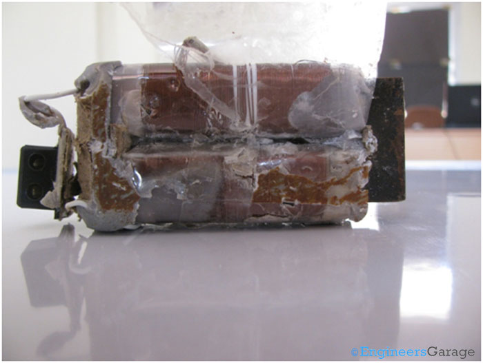
Image Showing Coils Present Inside Magnetic Ballast

Fig. 7: Image Showing Coils Present Inside Magnetic Ballast

Further incisions reveal the coils to be wound over a laminated ferrite core. The ferrite core has desirable properties like high magnetic permeability and low electrical conductivity which help reduce losses like eddy currents. Multiple layers of coils, separated by insulators, are wound around the core. Since the magnetic ballast works at 230V supply, a heat sink is essentially required to keep the device from overheating when subjected to longer hours of operation. The purpose is solved by the fiber glass reinforced polyester resin and the Aluminum casing of the ballast.

 Core

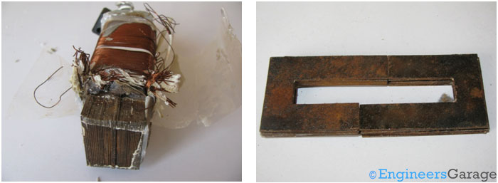
Magnetic Ballast Core

Fig. 8: Magnetic Ballast Core

The image above (left) shows the transformer core. It is made up of several thin ferrite frames as shown in the picture above (right) and has multiple layers of coils over it; the coils are insulated from each other with the help of cardboard paper. The use of multiple layers of windings is to increase the inductance of the coil in a relatively short space. The ferrite core is made by placing stacks of thin “U” thin metal plates. 
Magnetic ballasts have a major advantage over electronic ballasts that they can be recycled other than that they are very cheap. Moreover, they serve for longer time durations and can be repaired unlike the PCB based electronic ballasts.


Filed Under: Insight
Tagged With: ballast, coils, core, magnetic ballast
 

Next Article

← Previous Article
Next Article →

Questions related to this article?
👉Ask and discuss on EDAboard.com and Electro-Tech-Online.com forums.


Tell Us What You Think!! Cancel reply

You must be logged in to post a comment.

EE TECH TOOLBOX

“ee
Tech Toolbox: 5G Technology
This Tech Toolbox covers the basics of 5G technology plus a story about how engineers designed and built a prototype DSL router mostly from old cellphone parts. Download this first 5G/wired/wireless communications Tech Toolbox to learn more!

EE Learning Center

EE Learning Center
“engineers
EXPAND YOUR KNOWLEDGE AND STAY CONNECTED
Get the latest info on technologies, tools and strategies for EE professionals.

HAVE A QUESTION?

Have a technical question about an article or other engineering questions? Check out our engineering forums EDABoard.com and Electro-Tech-Online.com where you can get those questions asked and answered by your peers!


RSS EDABOARD.com Discussions

  • Identification of a 6 pin smd chip (sto-23-6) marked E2
  • Dynacord enter protect
  • IGBTs without negative gate drive
  • Need suggestions in task NI6363 retrigger (analog trigger)
  • Monte-Carlo simulation error on ADE-XL

RSS Electro-Tech-Online.com Discussions

  • Fun with AI and swordfish basic
  • Does US electric code allow branching ?
  • Sump pit water alarm - Kicad 9
  • turbo jet fan - feedback appreciated.
  • SiC FET disadvantages

Featured – LoRa/LoRaWan Series

  • What is the LoRaWAN network and how does it work?
  • Understanding LoRa architecture: nodes, gateways, and servers
  • Revolutionizing RF: LoRa applications and advantages
  • How to build a LoRa gateway using Raspberry Pi
  • How LoRa enables long-range communication
  • How communication works between two LoRa end-node devices

Recent Articles

  • How IoT network topologies work
  • The top five AI startups to watch in 2025
  • STMicroelectronics unveils SoC based on secure MCU
  • Nexperia’s 48 V ESD diodes support higher data rates with ultra-low capacitance design
  • Taoglas releases Patriot antenna with 18 integrated elements covering 600 to 6000 MHz

EE ENGINEERING TRAINING DAYS

engineering

Submit a Guest Post

submit a guest post
Engineers Garage
  • Analog IC TIps
  • Connector Tips
  • Battery Power Tips
  • DesignFast
  • EDABoard Forums
  • EE World Online
  • Electro-Tech-Online Forums
  • EV Engineering
  • Microcontroller Tips
  • Power Electronic Tips
  • Sensor Tips
  • Test and Measurement Tips
  • 5G Technology World
  • Subscribe to our newsletter
  • About Us
  • Contact Us
  • Advertise

Copyright © 2025 WTWH Media LLC. All Rights Reserved. The material on this site may not be reproduced, distributed, transmitted, cached or otherwise used, except with the prior written permission of WTWH Media
Privacy Policy

Search Engineers Garage

  • Electronic Projects & Tutorials
    • Electronic Projects
      • Arduino Projects
      • AVR
      • Raspberry pi
      • ESP8266
      • BeagleBone
      • 8051 Microcontroller
      • ARM
      • PIC Microcontroller
      • STM32
    • Tutorials
      • Audio Electronics
      • Battery Management
      • Brainwave
      • Electric Vehicles
      • EMI/EMC/RFI
      • Hardware Filters
      • IoT tutorials
      • Power Tutorials
      • Python
      • Sensors
      • USB
      • VHDL
    • Circuit Design
    • Project Videos
    • Components
  • Articles
    • Tech Articles
    • Insight
    • Invention Stories
    • How to
    • What Is
  • News
    • Electronic Product News
    • Business News
    • Company/Start-up News
    • DIY Reviews
    • Guest Post
  • Forums
    • EDABoard.com
    • Electro-Tech-Online
    • EG Forum Archive
  • DigiKey Store
    • Cables, Wires
    • Connectors, Interconnect
    • Discrete
    • Electromechanical
    • Embedded Computers
    • Enclosures, Hardware, Office
    • Integrated Circuits (ICs)
    • Isolators
    • LED/Optoelectronics
    • Passive
    • Power, Circuit Protection
    • Programmers
    • RF, Wireless
    • Semiconductors
    • Sensors, Transducers
    • Test Products
    • Tools
  • Learn
    • eBooks/Tech Tips
    • Design Guides
    • Learning Center
    • Tech Toolboxes
    • Webinars & Digital Events
  • Resources
    • Digital Issues
    • EE Training Days
    • LEAP Awards
    • Podcasts
    • Webinars / Digital Events
    • White Papers
    • Engineering Diversity & Inclusion
    • DesignFast
  • Guest Post Guidelines
  • Advertise
  • Subscribe