MCBs or Miniature Circuit Breakers are electromechanical devices which protect an electrical circuit from an overcurrent. The overcurrent, in an electrical circuit, may result from short circuit, overload or faulty design. An MCB is a better alternative to a Fuse since it does not require replacement once an overload is detected. Unlike fuse, an MCB can be easily reset and thus offers improved operational safety and greater convenience without incurring large operating cost.

Fig.1: Image of MCB

Fig. 2: Internal Specifications of MCB
Tripping mechanism of MCB

Fig. 3: ON State of MCB

Fig. 4: Coil Arrangement and Layout of Internal Parts
Connections of the coil
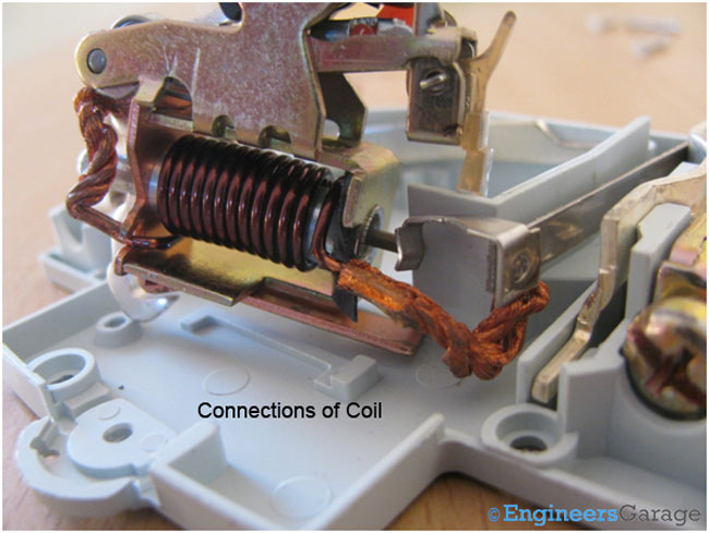
Switching Mechanism


Fig. 7: Plunger Mechanism
Role of Plunger
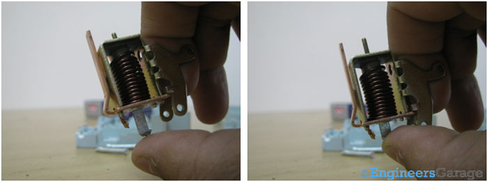
Fig. 8: Images showing Movement of Plunger
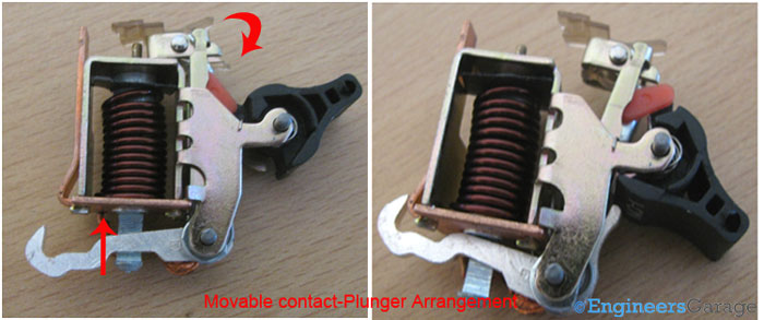
Fig. 9: Moveable Contact–Plunger Arrangement
Mechanical Assembly

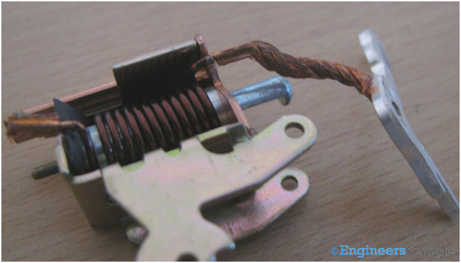
Fig. 11: Image showing Connection of Moveable Contact with Coil
Structure of Plunger
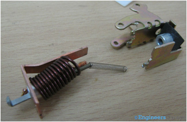
Fig. 12: Plunger and spring Arrangement

Fig. 13: Structure and Arrangement of Plunger, Moveable Contact, and Spring
Arrangement of mechanical parts
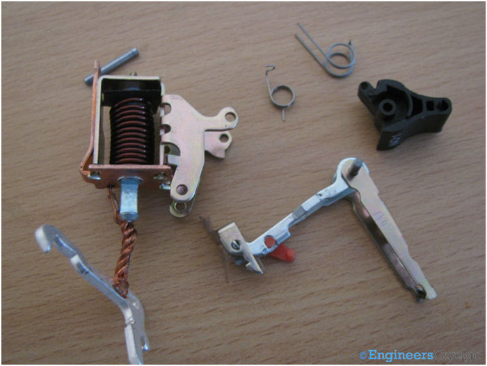
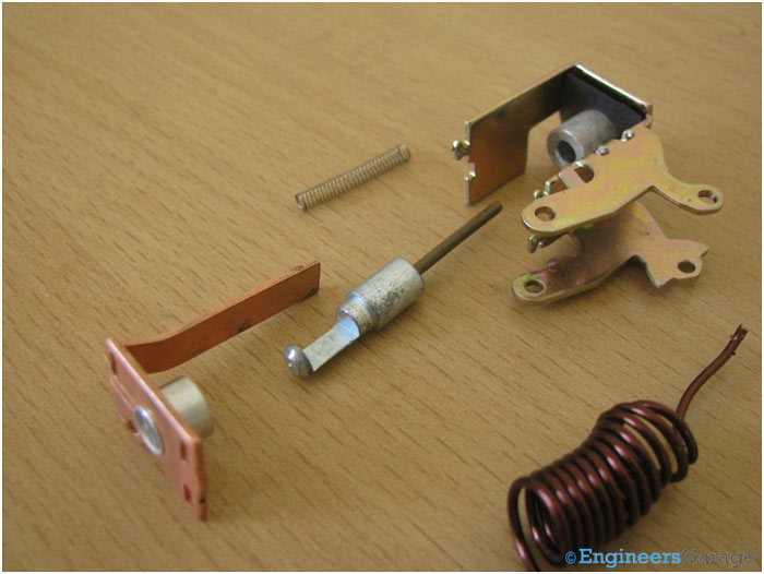
Fig. 15: Arrangement of Plunger, Coil, and Spring
Parts of MCB
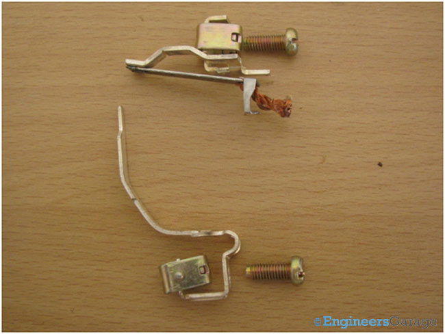

Fig. 17: Parts of Single Pole Assembly Parts
Arc quenching
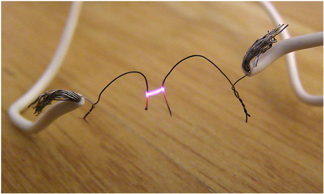

Fig. 19: Mechanism of Arc Production
Arc Chutes
The image below shows the arc chute used in the MCB for arc quenching purposes.

Fig. 20: Arc chute

Fig. 21: Mechanical Arrangement of Arc Chute

Fig. 22: Bimetallic Strips
Over heat protection
Filed Under: Insight


Questions related to this article?
👉Ask and discuss on Electro-Tech-Online.com and EDAboard.com forums.
Tell Us What You Think!!
You must be logged in to post a comment.