Some small devices and gadgets become so homogenous in our lives that we forget their importance is indispensible to us. One such electronic accessory is a multi-pin plug adapter. Acting as a single solution to connect multiple gadgets to a single power port, this small electrical equipment can create a big problem when absent.
Although multi pin adapter is a common accessory, a multi pin plug adapter, not many of the users would be aware that what is on the inside of this adapter. Is it a mesh of wires connecting to every port making a complex internal structure? How are the different connections protected from internal short circuiting? This insight will explore the details of the internal structures and their features of a 3-pin plug adaptor.
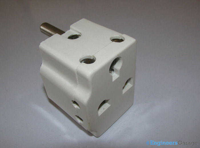
Fig. 1: Image of a 3-pin Plug Adaptor
A conventional multi plug adapter is cubical in its shape and has sockets on almost all sides except on the face which is plugged into power source.
The external structure consists of a two layer PVC casing which has sockets on various sides. The PVC coating is tough and sturdy to handle high mechanical stresses and impacts. It is mandatory for the PVC layers to tolerate higher temperature and heat input so that adapter can function for longer duration without compromising on user and gadget safety.
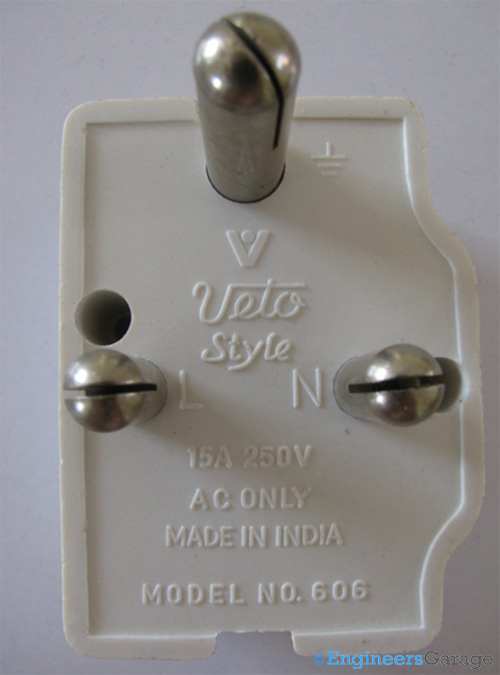
Fig. 2: Back of Switch Showing Printed Technical Specifications and Three Ports
The user relevant technical specifications are usually printed on the back of the switch by most manufacturers. As shown in the image above, the ground, live and neutral ports are indicated near their respective inputs.
Internal Structure
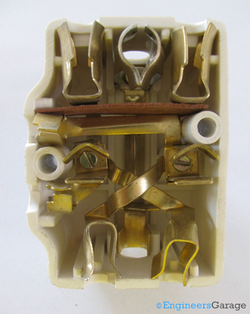
Fig. 3: Inside of Switch Showing Connections of Maze of Copper Wires
An interesting maze of connections can be seen after the outer casing layers are unscrewed and separated. This maze structure is formed by strips of copper and through them flows the current from the power socket to the electric device connected. The copper strips are shaped so that they can be easily accommodated in the adapter and do not touch each other. They have circular cut sections through which they are screwed together with the power ports of the adapter.
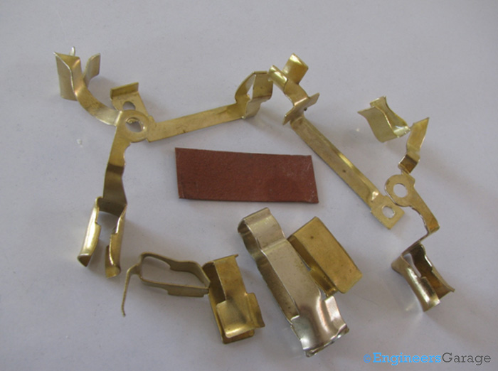
Fig. 4: Image Showing Copper Strips and their Shape
A copper strip can have one or two grooves where a plug can be inserted into it. In the instances of having one port, the other end of the strip terminates at the port of the adapter while in the cases of two; the connection with the adapter is established from the middle of the strip. A cardboard piece is used to separate two strips which are closely placed.
Copper Strips
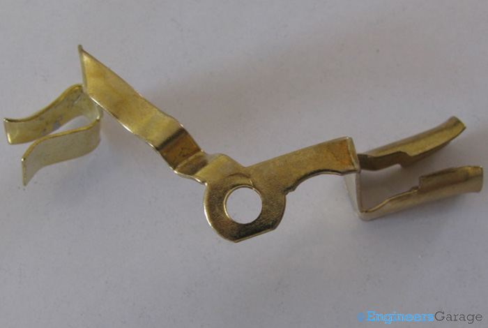
Fig. 5: Close up View of a Copper Strip Showing Circular cut Section
Copper strip with two input ports for plugs is shown in the image above. In the center, a circular cut section which is connects to the ports of the adapter can be seen.

Fig. 6: Single Input Groove of Copper Strip
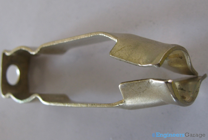
Fig. 7: Section of Copper Strip Which Connects to Power Ports
The images above show copper strips with single input grooves with sections at the other end from where they connect with the power ports.
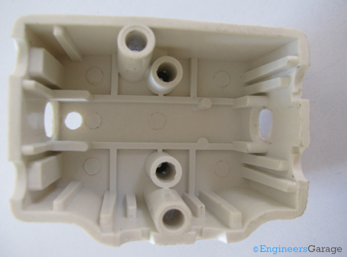
Fig. 8: Internal Structure of PVC Layer
The details of the shape of internal structure of the PVC layer can be seen after the copper strips are removed. Several latches have been placed on the inner walls to accommodate the strips in the desired manner.
Filed Under: Insight


Questions related to this article?
👉Ask and discuss on Electro-Tech-Online.com and EDAboard.com forums.
Tell Us What You Think!!
You must be logged in to post a comment.