Network resistor is a passive circuit element that is a combination of multiple resistances. It forms a convenient solution when the user needs multiple resistances while constructing a circuit. The manner in which the constituent resistances are combined can vary according to the circuit requirement.
Hence, this type of resistor can be used to condense the circuit with additional benefits of low costs and improved resistance tolerance matching.
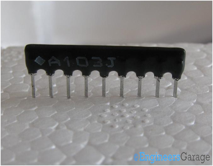
Fig. 1: Image of A103J 9-pin Network Resistor
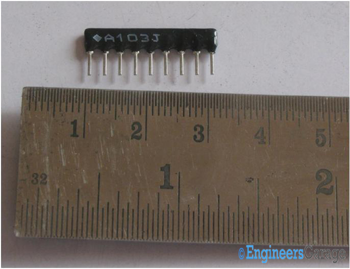
Fig. 2: Image Indicating the Small Size of Network Resistor
Image above shows an A103J 9 pin network resistor. It provides resistance from 10 Ohms to 4.7 Mega Ohms. The small size of the resistor is shown in the image above with the help of a centimeter scale.
Pin outs and Inner Ceramic
In the 9 pinned structure of the resistor, the first pin serves as the common terminal while the other 8 represent resistances. The pin that has a dot or a similar marking (quadrilateral in this case) is the first pin of the resistor.
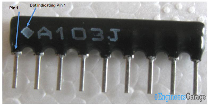
Fig. 3: Image showing Arrangement of Pins in Resistor
Image 03 shows the manner in which the resistor pins are placed. Fairly distant from each other, the pins can be thoroughly wired without the risk of them being short circuited.
While one end of the pins serves the purpose of connecting to the circuit, their other end is embedded inside the black polymer coating upon which the model number is printed.
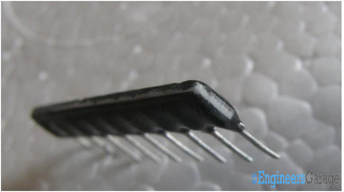
Fig. 4: Image showing Black Polymer Coating where Pins are Embedded
Though the polymer layer is thin, it is nicely adhered to the insides and requires a patient process of chipping. The ceramic beneath shown in image04 lies just under the polymer layer.
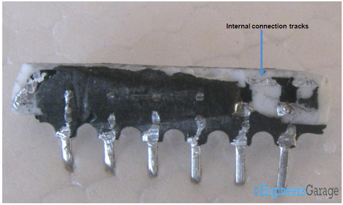
Fig. 5:Image showing Connecting Tracks of Pins inside Polymer Coating
Connecting Tracks & Pin Shape
Further chipping into the polymer layer reveals the manner in which the pins are placed. The internal connecting tracks, which have some part scrapped off due to chipping, also make their presence seen.
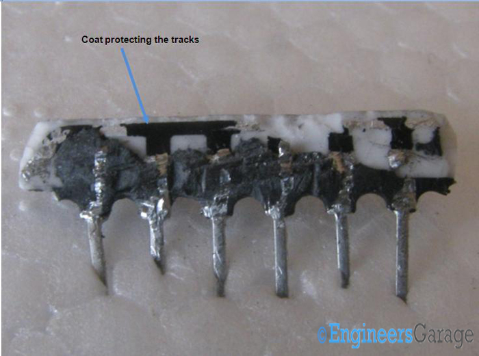
Fig. 6: Image Indicating Coat Protecting Connecting Tracks
Internal connection tracks are seen more clearly when more of the outer polymer layer is chipped off. Connecting up the 8 resistor legs to the common, the tracks have a black layer of paint above them which protects them from getting exposed to the outer coat of polymer. Thus, there are no unpredictable current losses.
Fig. 7: Image Indicating “Y”-Shaped Clamping of Legs
This image details the manner in which the legs clamp to the ceramic shell of the network resistor. The legs clamp up in a “Y” shape and adhere properly to the ceramic.
Filed Under: Insight


Questions related to this article?
👉Ask and discuss on EDAboard.com and Electro-Tech-Online.com forums.
Tell Us What You Think!!
You must be logged in to post a comment.