Relay is one of the most important electromechanical devices highly used in industrial applications specifically in automation. A relay is used for electronic to electrical interfacing i.e. it is used to switch on or off electrical circuits operating at high AC voltage using a low DC control voltage. A relay generally has two parts, a coil which operates at the rated DC voltage and a mechanically movable switch. The electronic and electrical circuits are electrically isolated but magnetically connected to each other, hence any fault on either side does not affects the other side.

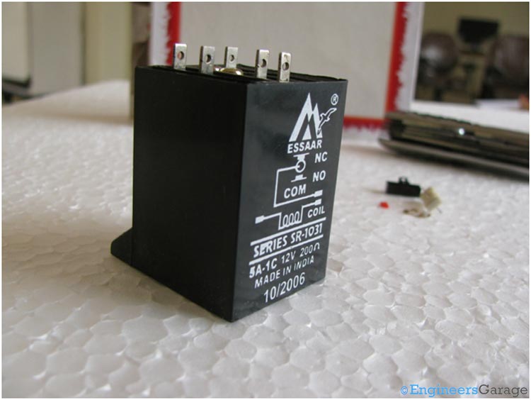
Fig. 1: Image of a Relay Switch

Fig. 2: Relay Switch with Five Terminals
Relay switch shown in the image above consists of five terminals. Two terminals are used to give the input DC voltage also known as the operating voltage of the relay. Relays are available in different operating voltages like 6V, 12V, 24V etc. The rest of the three terminals are used to connect the high voltage AC circuit. The terminals are called Common, Normally Open (NO) and Normally Closed (NC). Relays are available in various types & categories and in order to identify the correct configuration of the output terminals, it is best to see the data sheet or manual. You can also identify the terminals using a multimeter and at times it is printed on the relay itself.

Fig. 3: Internal Structure of Relay Switch
The internal structure of the relay is shown in the image above which is embedded inside the plastic covering.
Contact Mechanism

Fig. 4: Contact Mechanism of Relay Switch
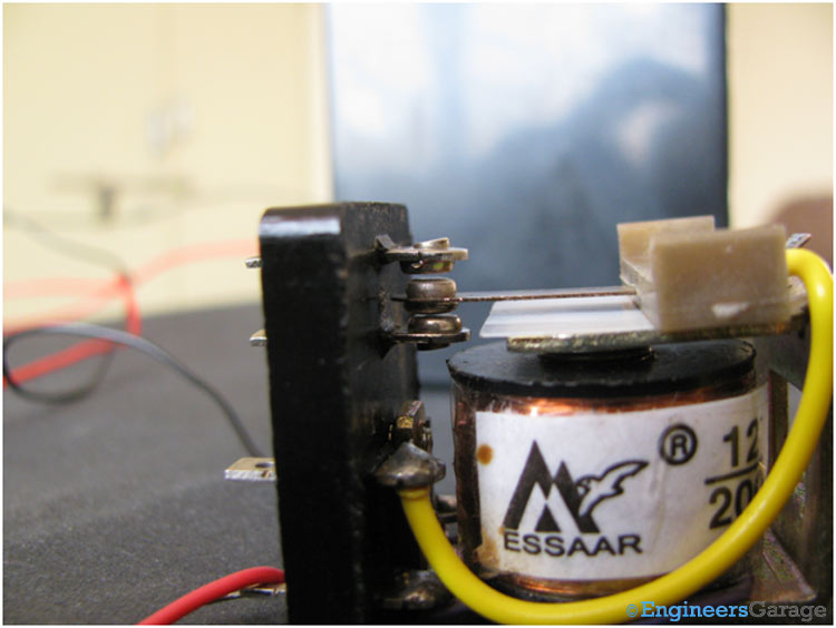
You can see a mechanically movable lever also called the common terminal. By default it remains in touch with one of the fixed terminal which is called the Normally Closed (NC) terminal. The other terminal which is not connected to the common point is called the Normally Open (NO) terminal.

Fig. 5: Normally Open (NO) Terminal
When we give the operating voltage to the relay coil, current starts flowing and it behaves as an electromagnet. The common terminal which is made up of iron gets pulled down by the electromagnetic force and gets connected to the Normally Open (NO) terminal as ahown in the figure above.
DC Coil & Spring

Fig. 6: DC Coil and Spring
The above image shows the DC coil used to create the necessary electromagnetic force when current is passed through the wires.

Fig. 7: Spring Connecting the Lever with NC Terminal
The above image shows the spring that keeps the lever in contact with the NC terminal when there is no current flowing in the coil.
Filed Under: Insight


Questions related to this article?
👉Ask and discuss on Electro-Tech-Online.com and EDAboard.com forums.
Tell Us What You Think!!
You must be logged in to post a comment.