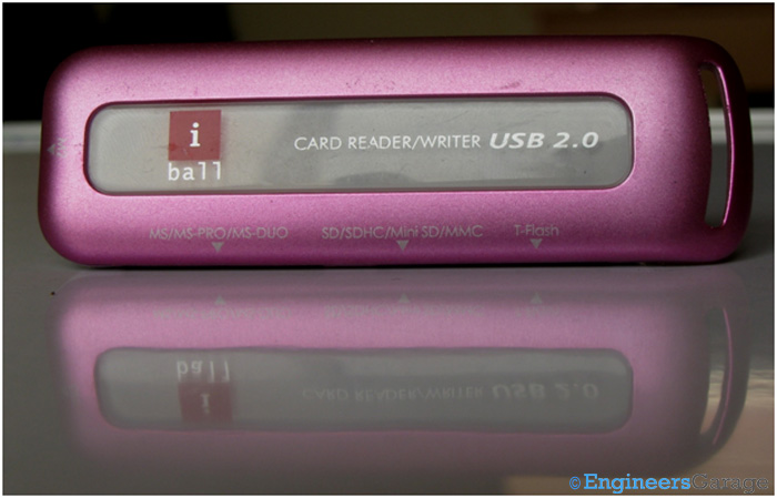
Fig. 1: SD Memory Card Reader
Secure Digital (SD) format is used by all major digital memory manufacturing companies of the world including giants like Sony and Siemens. SD cards are available in various memory capacities, sizes and data transfer speeds. The maximum size of the cards is that of SD or SD HC cards and the smaller ones require an adapter that scales them exactly to the size of a standard SD card. While most modern Laptops come with inbuilt SD card readers, devices that have only USB inputs require some kind of reading device to access or modify the data in the cards. SD card readers solve this purpose. SD card can be inserted inside the card slot in the readers which have a USB interface to connect to the desktop.
These readers are often designed to read multiple card formats such as MMC, T-Flash, Memory Stick and several others. For this purpose, they have multiple slots and are called Multi Slot Card Readers. Let’s find out the SD card reading features of one such Multi Slot Card Reader.
Outer Casing & PCB
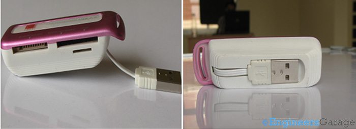
Fig. 2: Multiple Card Reader with USB Connector
A number of electronics equipment manufacturers are involved in manufacturing card readers under their brands. So, these card readers come in various designs and sizes depending upon the marketing strategy of the manufacturers. However, in order to minimize costs, most of these devices are packaged in plastic casings. Shown above is such a typical multiple card reader that has a USB connector emerging out of it.
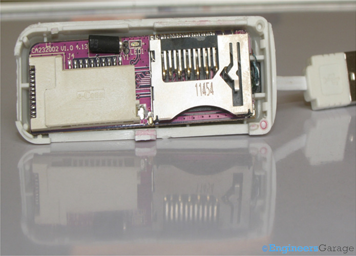
Fig. 3: SD card Slot: PCBA
On removing the top casing, a printed circuit board assembly (PCBA) appears. It holds the slot for SD card. Power supplied by the USB is sufficient to power these devices even when all the card slots are in use. So, the USB connector has a dual functionality of supplying power and carrying data and is preferred over any other protocol. The data exchange rates are determined by the version of USB interfacing used. USB v2.0, which provides up to 480Mbps of data transfer rate, is the norm. However, the speed of the memory card also plays a major role. On the casing of the memory card, a number is often printed and semi circled. The higher the number is, better are the data transfer speeds. The numbers printed usually are a multiple of 2, viz. 2, 4, 8.
The IC
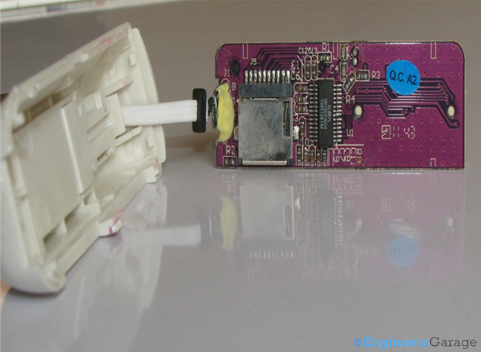
Fig. 4: IC Chip: 28 Pin GL827L USB Card Reader Chip
Removal of the rear casing reveals the IC that forms the heart of the card reader. The IC used is a 28pin GL827L USB card reader chip. Based on the 8051 series of microcontrollers, this IC powers the reader to access multiple types of memory cards. The IC chip has internal ROM that holds the necessary data exchange firmware which is burnt into it at the time of its manufacturing.
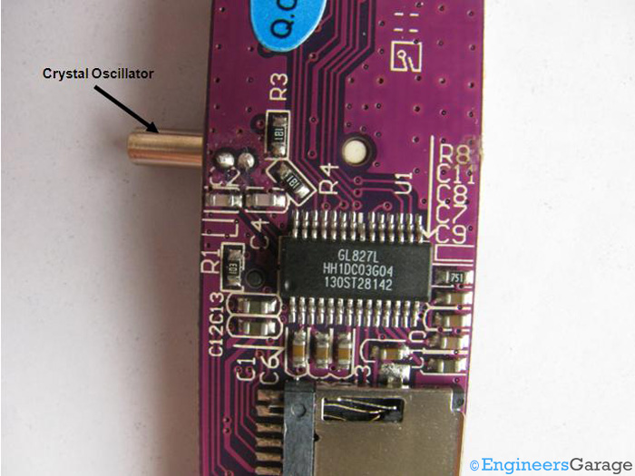
Fig. 5: IC Pin Arrangement and Crystal Oscillator
A 12MHz crystal oscillator is attached to clock the microcontroller based IC. The pin arrangement of the IC facilitates easy placement on the PCB.
Low quality readers that are quite economical in terms of cost have a COB IC instead of Surface Mount or Packaged ICs. COB IC based readers are generally of inferior quality than those with specialized external ICs mounted on the board and their performance fluctuates when reading cards or responding to locked cards.
Reader Casing
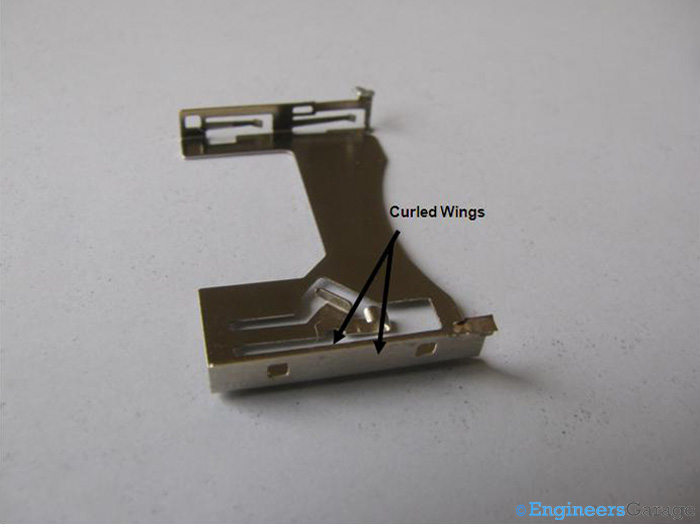
Fig. 6: Image Showing Curled Wings of SD Card Slot
The top casing of the SD card slot serves multiple purposes. A major function is to allow proper insertion of the card into the slot. Also, it has a slightly curled wing that makes a small “click” sound when the card is properly inserted. The curling of all pins ensures that the card doesn’t get scratched as it is inserted in the reader. The metallic casing also aids in responding to card locking mechanism which will be discussed shortly.
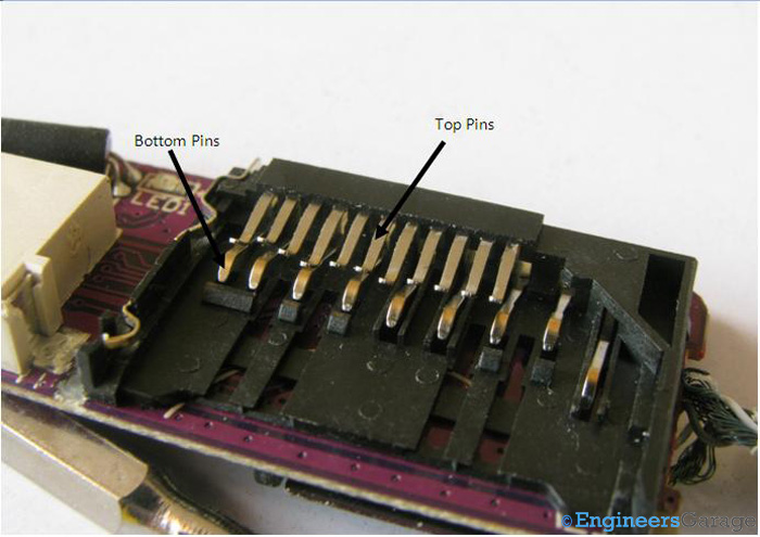
Fig. 7: Card Slot Configuration—Curved Top and Bottom Pins
Under the top casing, is a plastic structure loaded with pins on upper and lower sides. These pins are curved to provide a leaf spring action which helps in easy grip and secure connections and as previously mentioned, to prevent scratches. The pins on the top side serve the purpose of gripping the card when it is inserted. The bottom pins form connections with the pins of the card for data transfer. The upper and bottom pins must not touch each other. Accidental touches might generate a false signal indicating that a card has been inserted in the reader. In order to avoid false connections, the top and bottom pins are placed in an alternate fashion so that they never come in contact under normal circumstances.
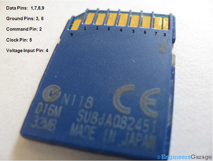
Fig. 8: Pin Configuration in SD Card
Every SD card has a 9 pin interface from where data exchanges take place. These pins have been named in the image shown above. The pins are placed in little deep channels in the card casing to avoid accidental shorting of any two pins. The connections on the reader being curved into leaf spring like shapes ensure secure connections.
Detection of Protected Mode
Detection of Locked (Read/Write) Protection Mode in SD Card
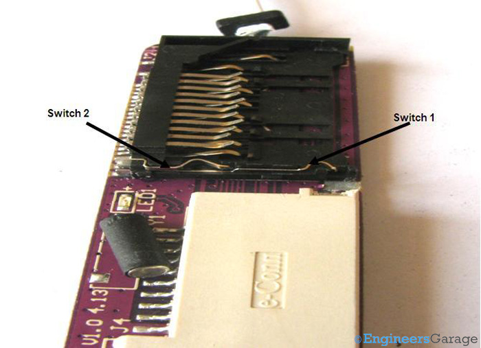
Fig. 9: Micro Lock Switches
A SD card often features a lock switch which if engaged, the data stored on the card cannot be modified. The ability to understand this locking feature depends on the card. Good quality cards have a micro switch combination that makes sure that when the lock is “ON”, the data remains safe.
Shown in the image above are two micro switches that aid in reading and writing data in the SD cards. These switches are not connected to each other in the reader. In the unlocked condition, they get connected by the top metallic casing of the reader while in the locked position, they remain intact. The mechanism is shown below:
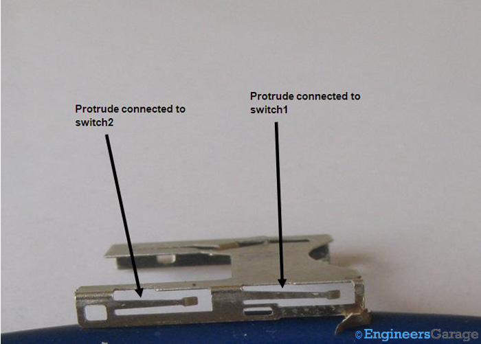
Fig. 10: Image Showing Two Protrudes that Facilitate Micro Lock Switch Connection
The metallic casing has internal protrudes so as to facilitate connections between the two switches. Switch 1 is needed to be elevated while swtich 2 gets connected to the casing as soon as the SD card is inserted to allow content modification in the card.
Protected Mode Contd.

Fig. 11: SD Card Case
Shown above is the case where an unlocked SD card is inserted into the reader. In this case, the lock lifts up the switch 1 so that it connects with the metallic casing which in turn is connected to the second switch enabling read-write operation.
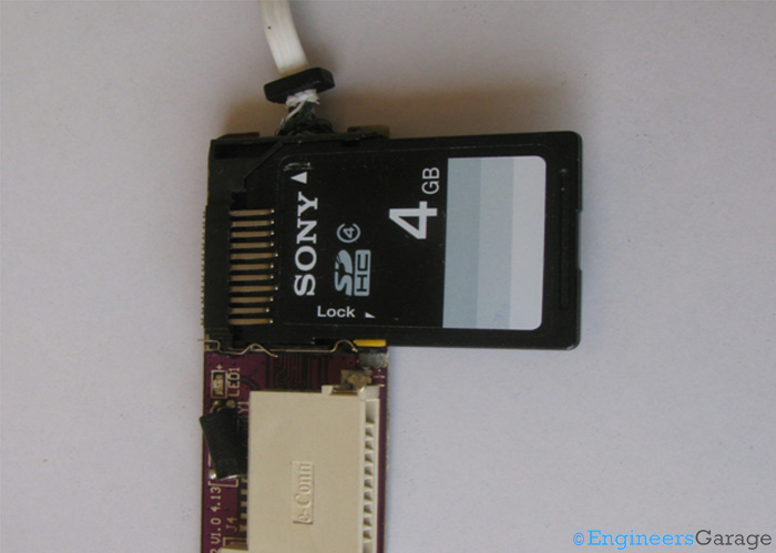
Fig. 12: SD Card Slot
In the case when lock is deactivated, switch 1 is placed near the lock switch and is unable to make contact with the metallic casing. Thus no connection between the switches is made. The data in the card is then write/read protected and cannot be modified.
Reading/Writing data on the Memory Card
Reading/Writing data on the Memory Card
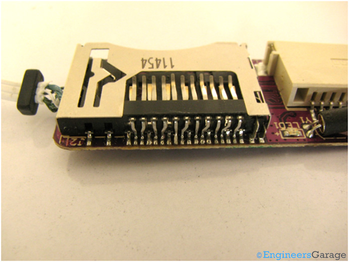
Fig. 13: Interconnections of Pins of Card Reader
When the Memory card is not locked, data exchange takes place between the host device and the card reader as and when the host requires. The pins of the reader are connected to the pins of the SD card and transfer the data to the IC. The IC then transfers it to the host and vice versa. The USB interface provides data transceiver function along with high speeds for smooth data exchange.
Filed Under: Insight


Questions related to this article?
👉Ask and discuss on EDAboard.com and Electro-Tech-Online.com forums.
Tell Us What You Think!!
You must be logged in to post a comment.