In 1910 Frank W. Wood made a board which can display number and after several modifications, today it’s called 7-segment display. 7 segment display is a 10 pin electronic component with eight led’s embedded inside it to displays number from 0 to 9.It is available in two configurations: common cathode and common anode. All the 8 LED terminals have their one end internally shorted and linked with the middle pins such that it serves as a common terminal (cathode or anode). Middle pin of both sides are shorted with each other which serves as a common terminal. 7 led are used to form the digits while the 8thone is for the dot which helps in identifying the correct orientation.
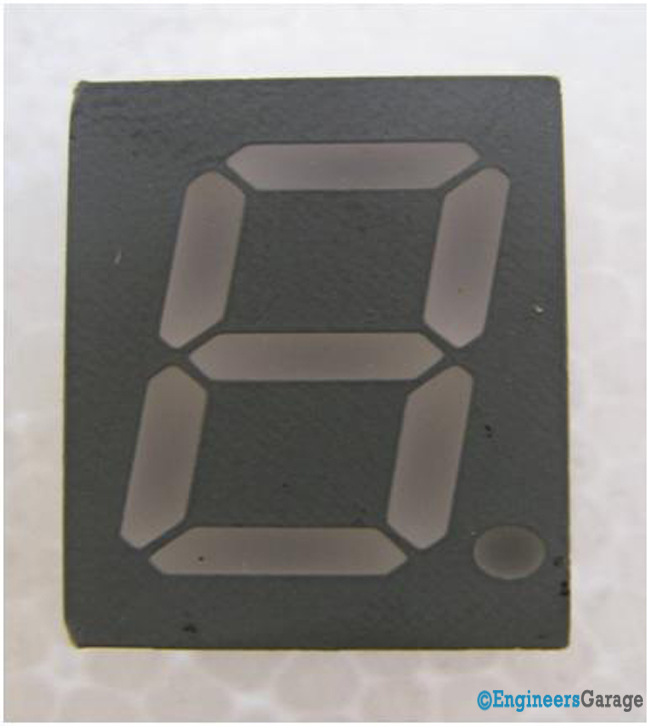
Fig. 1: Image of a 7-Segment Display
Top & Bottom View
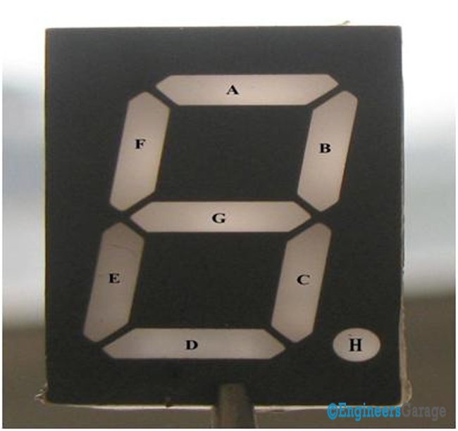
Fig. 2: Image Showing the Eight Fragments of 7-Segment Display
From the top view we can see the7-segment is divided into 8 fragments and is marked in a sequential manner. Let’s say we want to display 1 then B and C fragments will glow for 2 A, B, D, E, F will glow. The remaining numbers are displayed in the same manner. Though it is called as seven segments, it has eight LEDs. The seven LEDs are used to display the numbers & characters and the eighth one is used for glowing the dot. Pictorial description is shown above in Fig.2.
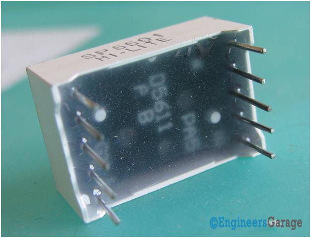
Fig. 3: Bottom Configuration and Parts of 7-Segment Display
Bottom image of 7 segment display is shown in the Figure 3.
Internal Structure and Circuit
BREAKING IN:
It is very hard to break this type of small component because of size and tight packaging. We broke the component in two parts i.e. display and the circuit segment. Both parts are surrounded by an insulating material made of ceramic, glass and plastics which helps the display and the circuit segment to remain intact. The device is packed using glue like thing which solidifies on cooling and then coated with desired substance to give attractive looks.
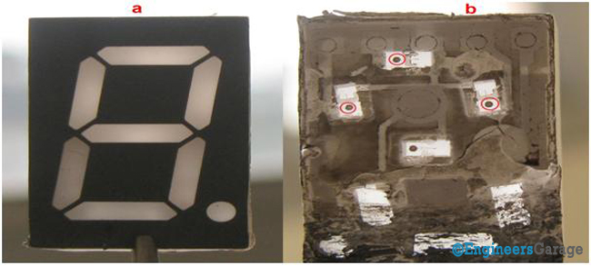
Fig. 4: (a) 7-Segment Display. (b) Corresponding Circuit Structure
Fig 4.a shows the front of the display which is same as described in the introduction.
On flipping the front part the fig 3b shows the inner view of the display. The small dots encircled in fig 4b are the semiconductor or LED wafer with a small wire attached to them called whisker. This image also shows that how the insulating material surrounds the inner view of display.
HOW IT WORKS:
At Engineers Garage, we are more curious to know how this stuff works instead of what this stuff do. So let’s start with it.
Circuit
After breaking in the actual pin diagram was visible which shows us how the LED’s are placed and their interconnections which helps in displaying digits. The internal shorting of the common pins on both sides is shownby blue line in Fig 5.
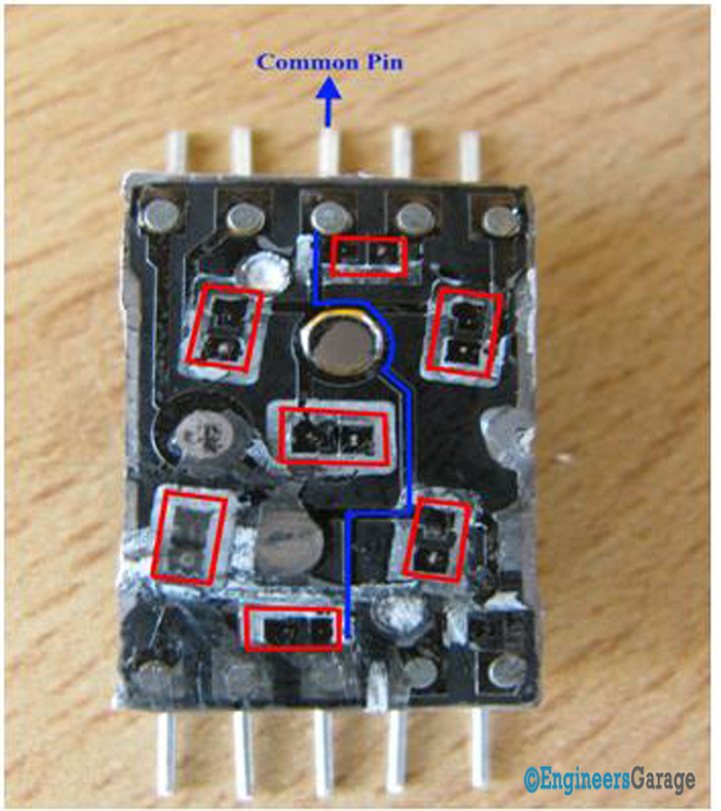
Fig. 5: Image Showing the Functional Mechanism of 7-Segment Display
The LED terminal gets the voltage supply from the remaining pins. The Red rectangular boxes in Fig 4 show various LED terminals. When voltage is given to a pin then its respective LED terminal gets the power and the LED glows. The circuit is designed in such a way that voltage at various pins can be applied at a same time.
Display
Display:
The display unit is divided into various fragments. These fragments comprises of small plastic particle with LED in housed into them as shown in Fig. 6
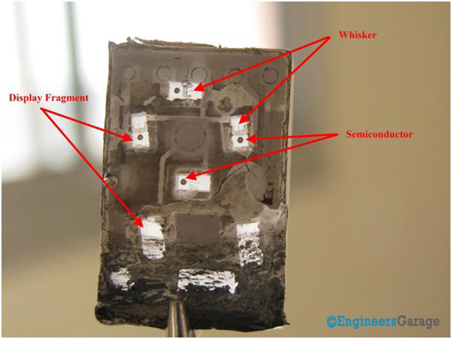
Fig. 6: Image Indicating the Various Fragments of Display Unit
A semiconductor or LED wafer is a PN junction Diode which emits light when the electrons combine in the active region. Whisker is a wire as thin as hair.When the back side is placed onto the circuit whisker gets linked with the LED terminal. When the supply is given to the terminals the connection of the LED gets completed and it displays the digit.
Filed Under: Insight


Questions related to this article?
👉Ask and discuss on EDAboard.com and Electro-Tech-Online.com forums.
Tell Us What You Think!!
You must be logged in to post a comment.