Slide switches are one of the most common switches used in electrical devices. Compact sized and operable with only a finger, slide switches are important as their absence can render the device useless in absence of the capability to switch ON and OFF without having to pull the mains cord. It is uncanny to list all the applications where slide switch is used. From electrical chimneys to hand blender in the kitchen, from lamp to the toy car in the living room, slide switches are almost omnipresent.
We are used to see switches and use it as a black box. But have you ever thought how does a slider of few centimeters control big machines? What happens inside the switch when it makes and breaks the connection? Is it an assembly of several even smaller components? Why does it keep on working irrespective of the environmental conditions? Let’s find out the internal as well as external features of the switch that make it work.
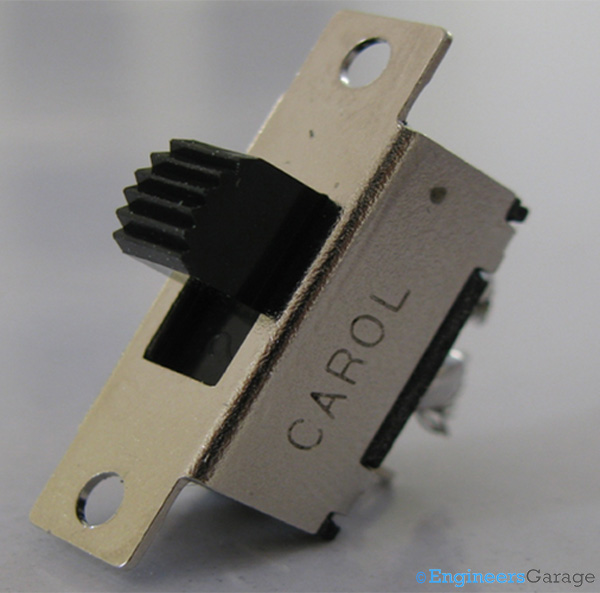
Fig. 1: Image of a Slide Switch
Outer Structure
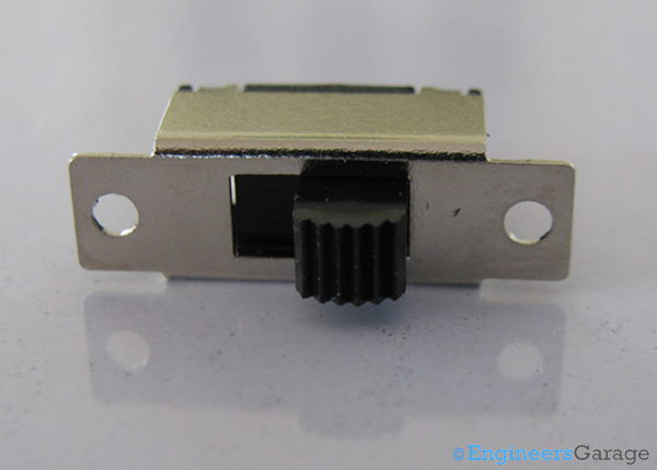
Fig. 2: Image of a Simple and Commonly used Slide Switch
Depicted in the image above is a common typical slide switch. This is a miniature type of slide switch and already has openings near its edges for easy mounting on electronic devices. Such a switch finds its applications in toy cars, microphones, radios, portable fans and all those devices that have a limited number of functions, usually ON and OFF.
The frame of the structure is casted from iron-nickel. Thin but tough, this frame protects the internal circuitry of the switch as well as defines the path for the slider to move.
Also appears in the outer structure, is the slider or actuator of the switch. This is the switching head of the device and like the frame, is quite tough. Made from ultra light weight (ULV) glass mixed epoxy material, the slider can tolerate high temperatures as well as stand significant mechanical forces.
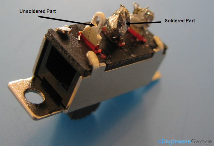
Fig. 3: Parts of Slide Switch on Rear Side
The rear part of the slide switch has the connecting terminals. As shown in the image above, the terminals can be easily soldered to the wires of the circuitry. To fulfill this purpose, they are made of copper that has nickel-copper plating over them.
It can be seen in the image above that how the metal frame is clamped to the internal structure of switch. To make the structure small and light, this serves as a convenient option and eradicates the requirement of any screws.
Internal Structure
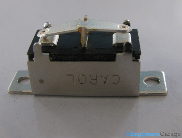
Fig. 4: Slide Switch Inner Structure
When the outer structure is removed, a see-saw structure is revealed. This structure is a movable contact that is made to touch either of the stationary contacts by the slider. The movable contact is placed on a fulcrum. To increase the longevity of the see saw process, fulcrum and the corresponding part of the movable contact are lubricated. This reduces wear and tear due to friction and sharp edges of the fulcrum.
The movable contact has two small bulges punched into it which touch the stationary contact when the slider is put on either side. The contacts as well as the fulcrum are made of copper which has silver plating over it. This serves the purpose of giving response even at the slightest of the changes that the switch can sense and silver being a noble metal does not react chemically with environmental compositions. The contacts are embedded on the same glass mixed epoxy polymer from which the slider has been made.
The given slide switch has two states: ON and OFF, a Single Pole Single Throw (SPST) type. However, it is observed that three connecting terminals are there. There are certain switches which have three modes: ON-OFF-ON or vice versa. These switches appear same as those mentioned in the image above and just have a slight different metal frame that could allow three states. In these types of switches, the movable contact can be made to stay at a balanced state where it isn’t touching any terminal. This position serves as the third state for the switch which requires the third terminal.
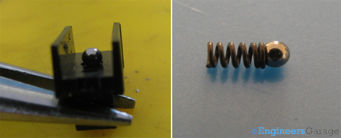
Fig. 5: First Part Showing Glass Epoxy Slider; Second Part Showing Assembly of Metallic Shell and Spring
The glass epoxy slider has a small hole on its inside where an assembly of a metallic shell and a spring rests. Whenever the slider is moved, the shell makes contact with the movable see-saw part of the switch and resides on its periphery where the switch is supposed to be ON or OFF. The spring ensures that the metal shell pushes the see-saw frame down to establish firm contact with the conductor below. The spherical shape is chosen so that it can roll on the see-saw with ease and minimal friction.
Working
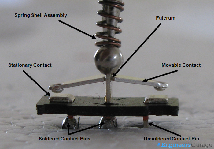
Fig. 6: Functional Mechanism of Slide Switch
Shown above is the switch that has two contacts soldered out of the three. The default state where the spring-shell assembly is at the fulcrum of the movable contact plate. This position is the default state for the switch and is usually taken as an off position. When shell is placed at the fulcrum, there is no contact between the stationary and movable contacts. The spring is in its coiled state at this resting position and cannot release since the fulcrum is immovable.
When the slider is moved towards any of the contacts, the shell is displaced from the top of the fulcrum and onto either side of the see-saw. This part being movable, allows the spring to uncompress itself and push the metal shell tight against the see-saw, which in turn is pushed downwards.
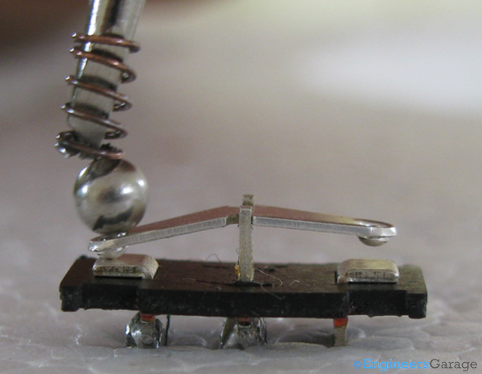
Fig. 7: Image Showing How the Metallic Shell and Spring Assembly Works Upon the Stationary Contact Points of Slide Switch
The shell and spring assembly make movable contact touch the stationary contact points beneath it as shown in the figure above. In this switch, only one stationary contact has its pin soldered, thus the other has no role. When all three contacts are used, combinations of switch On and Off states can be achieved. This one serves as ON-OFF or OFF-ON switch, depending on what the default state denotes. Slide switches are usually designed to work on household voltages (220-240V), though it is customary to refer to their design ratings for best performance and to avoid undesired side-effects. The parts used in the switch do not have any thin wires which might break off and disrupt the functioning and hence are quite robust. For devices that require more switches, an array of slide switches known as the DIP switch is used.
Filed Under: Insight


Questions related to this article?
👉Ask and discuss on EDAboard.com and Electro-Tech-Online.com forums.
Tell Us What You Think!!
You must be logged in to post a comment.