Fluorescent lights are among the most popular lighting system used worldwide. Fluorescent tubes/lamps are filled with mercury vapor. They use electric charge to excite mercury atoms in order to produce ultra violet light. A glow starter or commonly known as starter is used in the tube light circuit to provide an initial current to filaments of the tube light. To understand the purpose exactly why a starter is used in the tube light circuit, let’s look into its circuit.
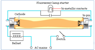
Fig. 1: Circuit Structure of Tubelight Starter
When the switch is pressed current cannot pass through the tube initially because the gas inside it is not ionized and hence the tube light circuit behaves as open circuit. Once the gas is ionized, it will provide a conduction path for the current to flow. In order to ionize the gas, an initial high current is required for a short period across the filaments of the main tube. That is what a starter does. A starter initially provides a path to complete the circuit and once tube light starts the current flows through the ionized gas in the main tube.
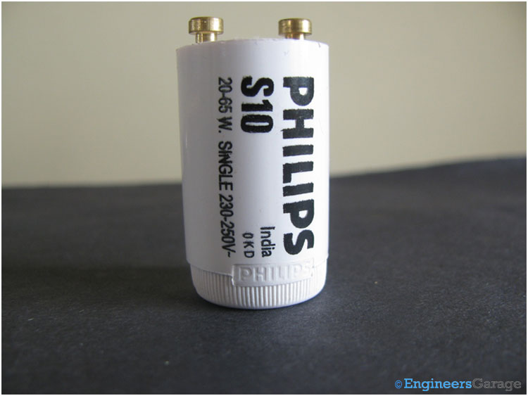
Fig. 2: Image of Tubelight Starter
The above image shows a typical starter connected in parallel with the fluorescent lamp.
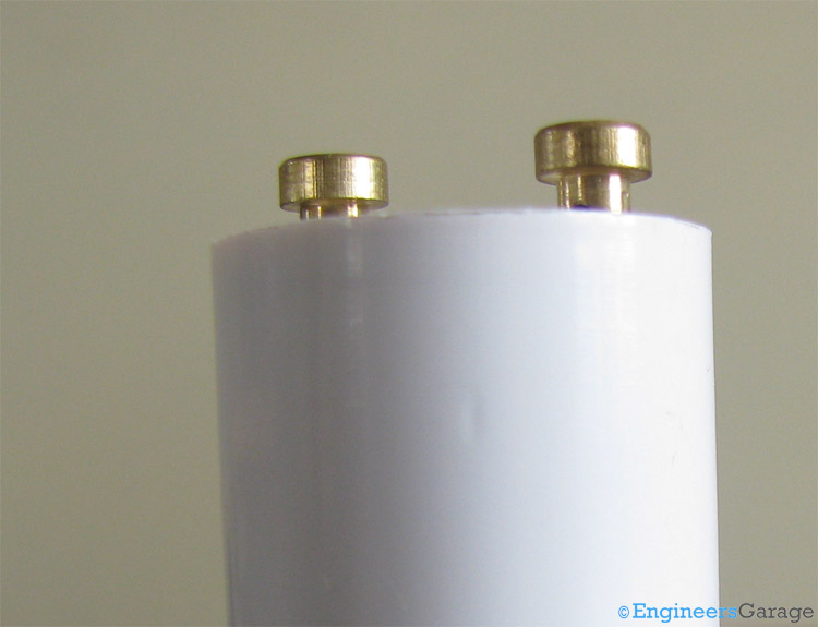
Fig. 3: Image Indicating the Cylindrical Shape of Starter with its Two Terminals Attached
It is a cylindrical can with two terminals, as shown in the above pictures. These two terminals are used to electrically connect the starter with the rest of the circuit.
Key Components

Fig. 4: Image Showing Gas-Filled Tube and RFI Suppression Capacitor of Starter
A starter incorporates a small gas filled tube and a RFI (Radio Frequency Interference) suppression capacitor (Also see Capacitor-Insight). Both the capacitor as well as neon gas filled tube are connected in parallel with tube light circuit.
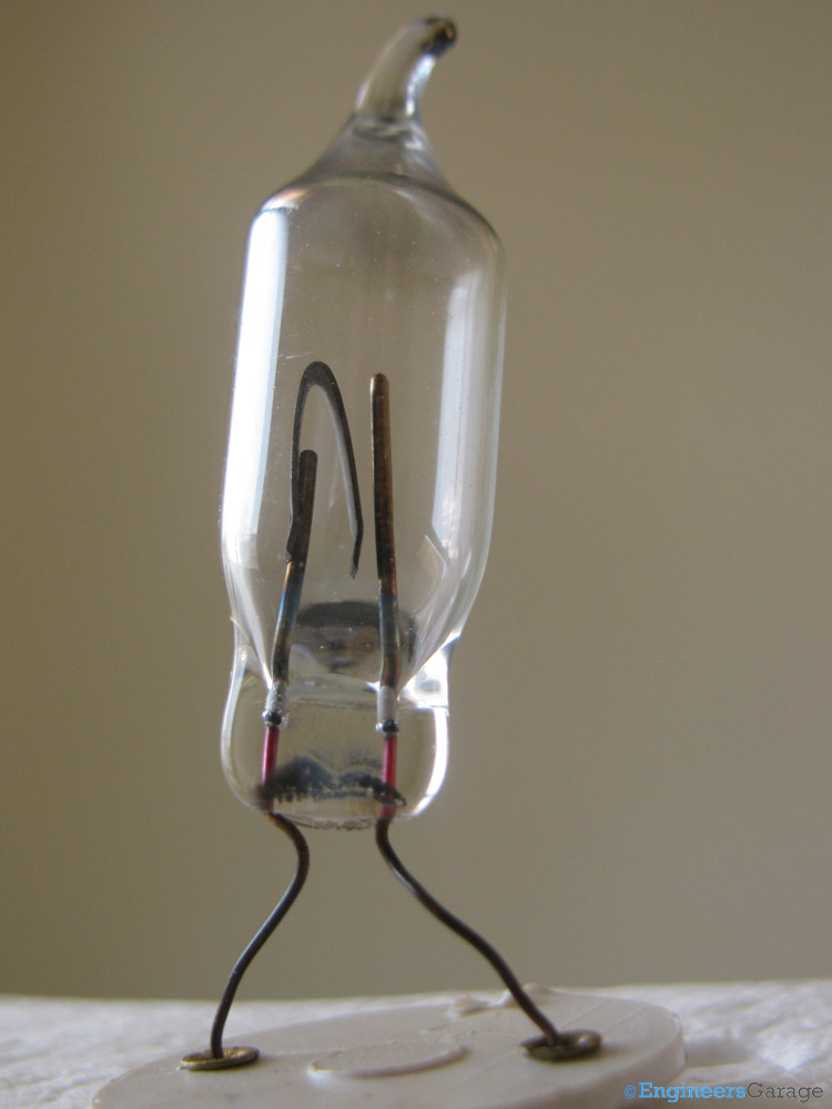
Fig. 5: Close-up View of Gas-Filled Tube
The small glass tube is filled with neon or argon and contains a bi-metallic plate. This bi-metallic plate is the heart of the starter. Among the two contact strips shown in the image, left one is attached with the bi-metallic strip as shown in the above image.
Capacitor
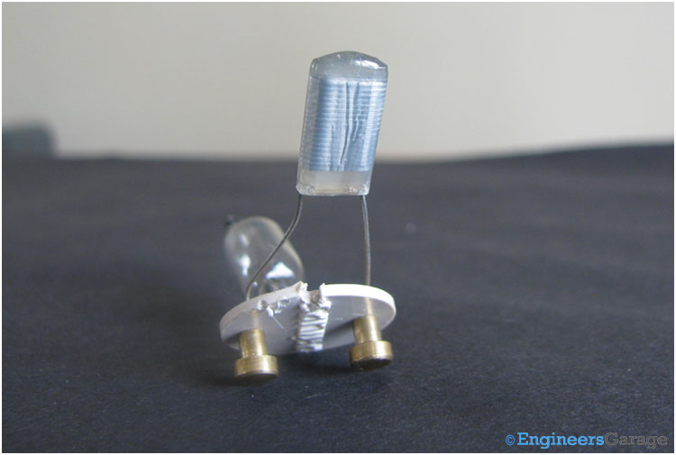
Fig. 6: Image of RFI Suppression Capacitor
A RFI suppression capacitor is shown in the image. Opening the capacitor unveils the subsequent view.
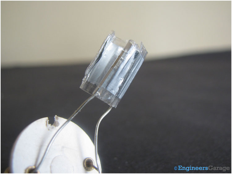
Fig. 7: Capacitor Insides
RFI suppression capacitor has the following functions in the tube light circuit:
a. Absorbs the electric noise created by discharge around the electrodes in order to suppress the radio frequency interference with other electric devices.
b. Attenuates the initial striking voltage from the ballast and make it wide too in order to ensure more reliable starting operation.
c. By avoiding arching between glow tube contacts, it ensures a long contact life.
Working:
When power is applied to a tube light circuit, this voltage is not sufficient to ionize the gas inside the main tube. However, this power generates an electric potential across the contacts of small tube of starter. This electric field is large enough to ionize the gas inside the small tube and hence a current flow in the two contacts through the ionized gas. The heat generated due to the flow of current expands the bi-metallic plate towards the other plate and within a few tenths of seconds, it touches the other plate. This serves two functions – first, it will de-ionize the gas and second, it will increase the current through the filaments of the main tube.
Now the gas of the main tube gets ionized and current starts flowing through it. Thus the bi-metallic plate of starter cools down re-opening the gap between the two contacts. This gap will remain open until the tube light will start next time.
Filed Under: Insight


Questions related to this article?
👉Ask and discuss on Electro-Tech-Online.com and EDAboard.com forums.
Tell Us What You Think!!
You must be logged in to post a comment.