Wire wound adjustable resistors or rheostats are high power rheostats that can provide variable resistances to the circuit over a certain range. Hence, these are widely used in those areas where circuits are often required to work at high temperatures. It differs from the potentiometer in terms of power handling capacity and construction.
External Assembly
The outer appearance of a wire wound rheostat gives an impression of a hollow cylinder having two thin lead connections at the sides of its terminal and a horse shoe shaped metal slider that has a nut bolt assembly at its open end. The ceramic and the wire wound assembly over it are covered by silicone. This coating ensures that the rheostat is tolerant to temperature variations, moisture, and oil and is very well electrically insulated. A lead wire wounded on the ceramic rod serves as the variable resistor. Shown below are some images of the outer view taken at various angles.

Fig. 1: Images Showing External View of A Wire Wound Adjustable Rheostat From Different Sides
Slider
The Slider
The horse shoe shaped slider plays a major role in changing the resistance of the rheostat. It has a slight protrude on its surface which touches the lead wire wound on the ceramic. One of the lead terminals forms the first end and this slider forms other end of the rheostat from where the resistance output has to be taken. This slider can be loosened to move and tightened to stay on the ceramic with the help of the nut and bolt assembly.
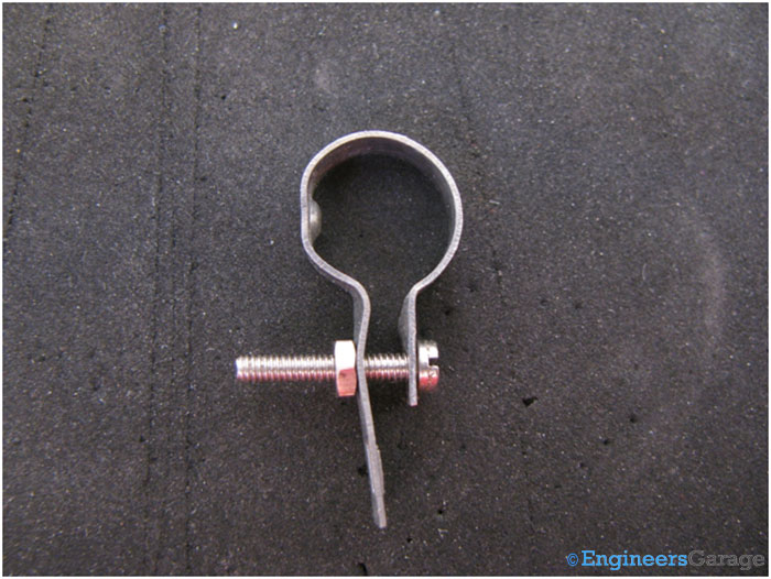
Fig. 2: Image Showing Slider of A Wire Wound Adjustable Rheostat
After slider is removed from the rheostat, it looks quite similar to a wire wound resistor. Only difference is that rheostat has some ceramic coating scrapped off to allow movement of the slider while the resistor is fully protected by the coating.
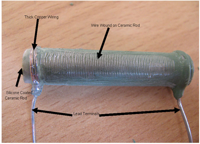
Fig. 3: Wire Wound Adjustable Rheostat External Structure After Removal of Slider
Internal Structure
After removing the silicone sheath from the terminals where the leads are connected, thick copper wiring is done to which the leads are strongly adhered through soldering.
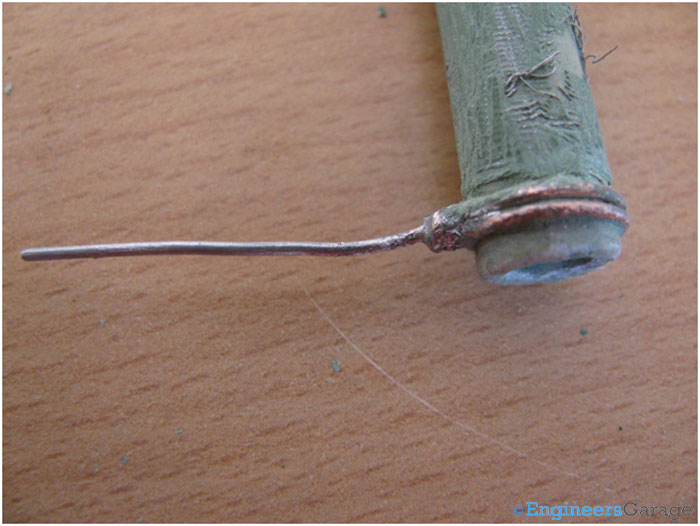
Fig. 4: Image Showing Copper Wiring In An Adjustable RHeostat
The hollow ceramic cylinder is not tough mechanically and can be easily split into two. The wire that is wound over can also be easily unfolded after the splitting.
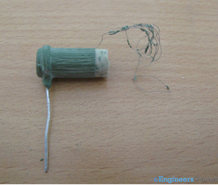
Fig. 5: Hollow Ceramic Cylinder
As the wire is removed, simultaneously the coating is also scrapped off the ceramic as it is adhered to the wire till the point where copper wire is done over it.
Ceramic Cylinder
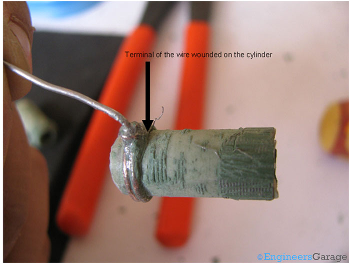
Fig. 6: Closer View of Ceramic Cylinder
The bare ceramic cylinder is white in colour and from the inside has been coated by the silicone so that rheostat is safe even from the ambient adversities that can have a direct impact on its working.
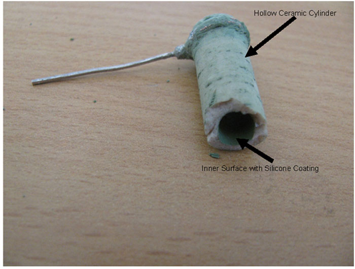
Fig. 7: Image Showing Various Parts of Ceramic Cylinder
Filed Under: Insight


Questions related to this article?
👉Ask and discuss on Electro-Tech-Online.com and EDAboard.com forums.
Tell Us What You Think!!
You must be logged in to post a comment.