Engineers Garage

  • Projects and Tutorials
    • Electronic Projects
      • 8051
      • Arduino
      • ARM
      • AVR
      • PIC
      • Raspberry pi
      • STM32
    • Tutorials
    • Circuit Design
    • Project Videos
    • Components
  • Articles
    • Tech Articles
    • Insight
    • Invention Stories
    • How to
    • What Is
  • News
    • Electronic Products News
    • DIY Reviews
    • Guest Post
  • Forums
    • EDABoard.com
    • Electro-Tech-Online
    • EG Forum Archive
  • Digi-Key Store
    • Cables, Wires
    • Connectors, Interconnect
    • Discrete
    • Electromechanical
    • Embedded Computers
    • Enclosures, Hardware, Office
    • Integrated Circuits (ICs)
    • Isolators
    • LED/Optoelectronics
    • Passive
    • Power, Circuit Protection
    • Programmers
    • RF, Wireless
    • Semiconductors
    • Sensors, Transducers
    • Test Products
    • Tools
  • EE Resources
    • DesignFast
    • LEAP Awards
    • Oscilloscope Product Finder
    • White Papers
    • Webinars
  • EE Learning Center
  • Women in Engineering

Insight – How XLR Connector Works

By Ashutosh Bhatt

Every year, technology sector companies invest millions of dollars in R&D to improve their products and release new products. An important part of these products is characterized by the connectors they use. For instance, a computer requires USB and PS2 Connector, a headphone requires TRS connector and a telephone requires RJ11 connector and so on. For high quality professional sounds, XLR connector is widely preferred. The term XLR derives its name from Cannon “X” series (where it was first used). Terms “L” and “R” are derived from latch and rubber used in the connector.
From a good microphone to a tuned guitar, all gadgets should be well matched up to the needs of the performer. Playing a critical role in professional audio applications is an XLR connector. Connecting the microphone to the amplifier, these connectors form an indispensible part of any electric instrument.
 
A 3 pin connector specifically designed for audio applications, XLR are known to be used in almost every wired microphone. Let’s get into the internal structure of the connector and discover various parts that make the connector function.
 
Front View of 3-pin XLR Connector
 
Fig. 1: Front View of 3-pin XLR Connector

Front Structure

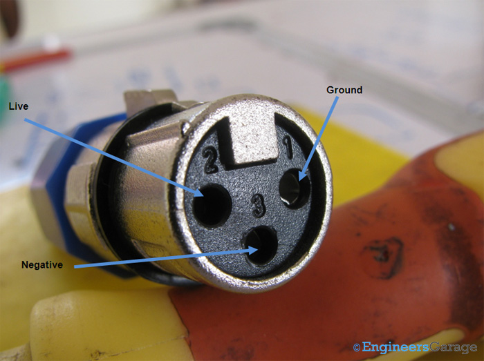
Front Structure: The image above shows front view of a 3 pin XLR connector. The connector is made up of alloy (usually of zinc) and plastic.
There are three pins to take the input from the microphone. A small steel latch locks the microphone with the connector.
 
Input Pins and Labels for Wire Combination
 
Fig. 2: Input Pins and Labels for Wire Combination
 
Input Pins: The inputs are labeled from 1 to 3 which aids in identifying the right pins when the wiring of the connector is done. In a professional sound system, inputs 1, 2 and 3 get the following wire combination:
·                     Input 1 for Ground
·                     Input 2 for Live
·                     Input 3 for Negative
 
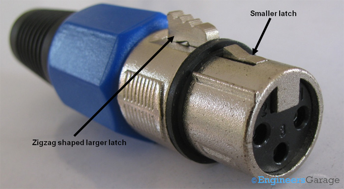
Image Indicating the Latch-Based Lock Mechanism of XLR Connector
 
Fig. 3: Image Indicating the Latch-Based Lock Mechanism of XLR Connector

Locking the device

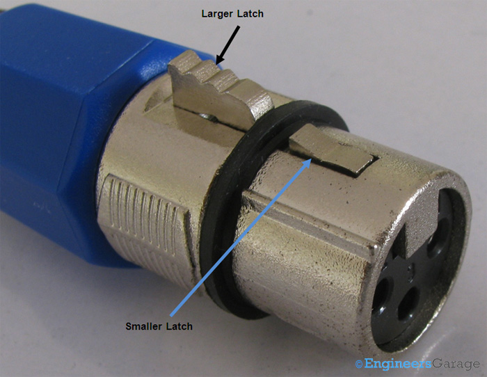
Locking the device: It is very essential for any connector to connect tightly to its corresponding device. A latch based locking mechanism solves this purpose in a microphone.
The larger latch is accessible to the user while the smaller one hides under the device. A rubber ring protects the device from wear and tear.
In order to disconnect the device, the larger latch is pressed which in turn presses the smaller latch. The device can be then removed from the XLR connector.
 
Rubber Ring of Connector
 
Fig. 4: Rubber Ring of Connector
 
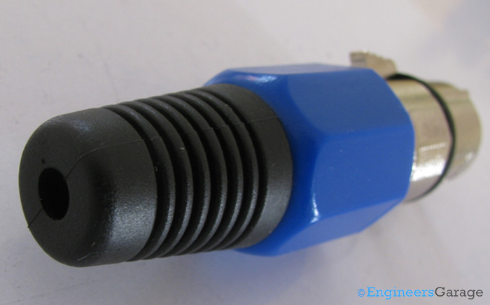
Rear View: The rear side of the connector is the output part from which the wire extends out. The blue colored plastic casing helps in griping the connector to connect or disconnect. The black rubber casing which is called the sleeve keeps the wire straight thereby  avoiding any mechanical damage to the connections.
 
Image Showing Connection of Plastic Casing with Alloy Structure
 
Fig. 5: Image Showing Connection of Plastic Casing with Alloy Structure
 
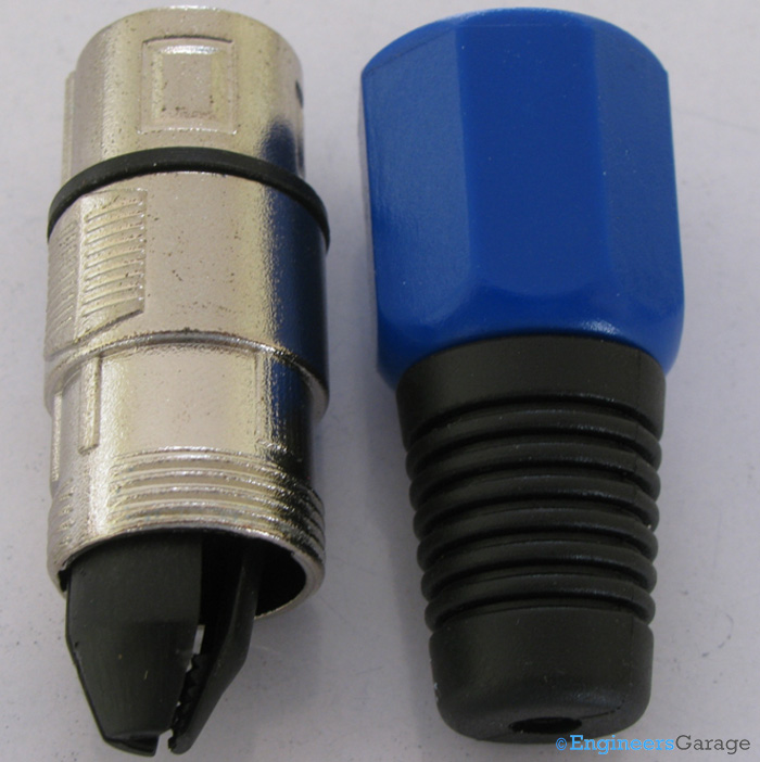
The image above shows the connection of the plastic casing with the alloy structure.
 
Layout of Alloy Structure Indicating the Bullet-like Projection at its End; Plastic Casing on Right
 
Fig. 6: Layout of Alloy Structure Indicating the Bullet-like Projection at its End; Plastic Casing on Right

Wire Streamliner

Wire Streamliner: When separated, the alloy region has an inverted bullet like plastic coming out of its bottom. This part streamlines the wires inserted to connect to the pins of the connector.
 
Image Showing Interface for Wires
 
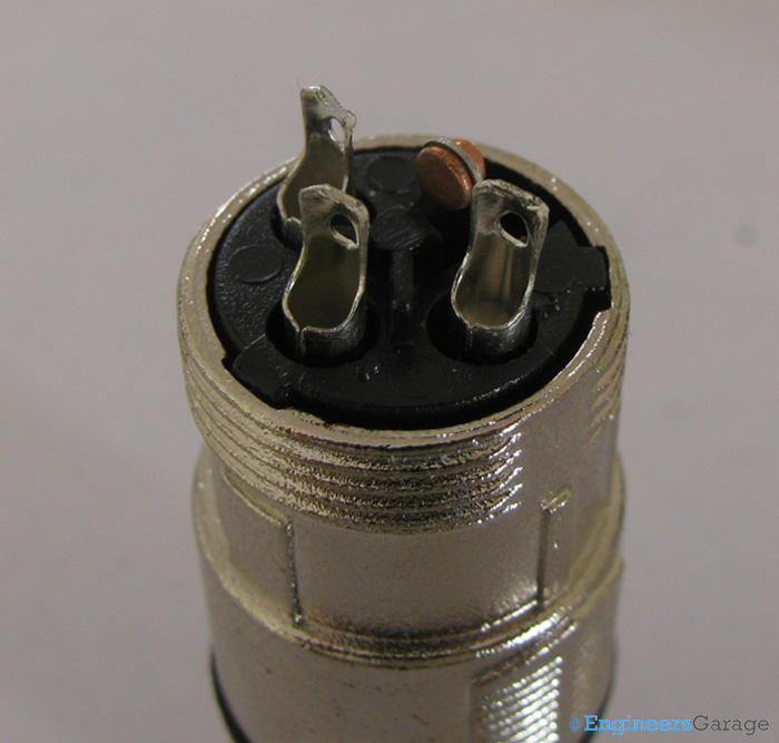
Fig. 7: Image Showing Interface for Wires
 
Interface for Wires: The image above shows the pins of the connector where the wires are soldered.
 
Lever for Latch Movement
 
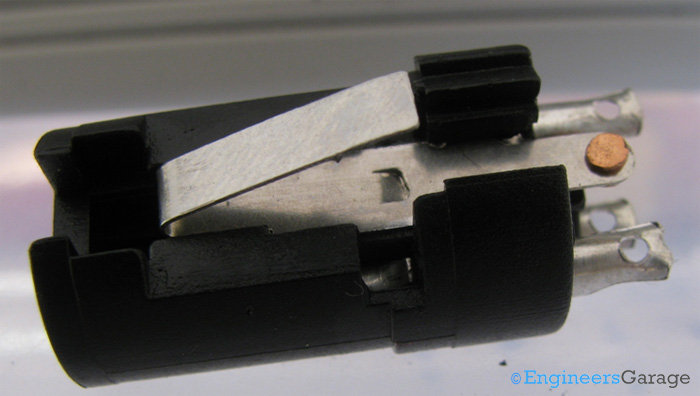
Fig. 8: Lever for Latch Movement

Lever for Latch movement

Lever for Latch movement:  The latches placed on the connector for holding the device have a vertical back and forth movement because of a lever placed beneath them. This lever structure gets pressed whenever the device has to be disconnected and as soon as force gets off, it places the latches back in their rest state. Thus, having a spring like motion to assist latch movement is the prime function of the lever.
 
Image Showing Mechanism for Holding Pins in Connector
 
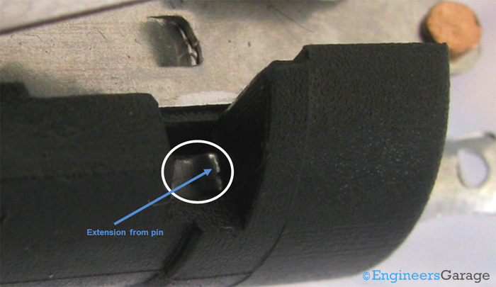
Fig. 9: Image Showing Mechanism for Holding Pins in Connector
 
Holding the input pins: The image above shows a small section through which the pins of the connector are held. The input pins are firmly held in the plastic mould which restrict their movement. The pins also have certain extensions that limit their movement beyond a certain limit.
 
Image Showing Structure of XLR Pins
 
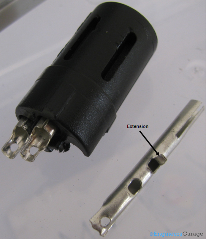
Fig. 10 Image Showing Structure of XLR Pins

The connecting pins have a structure similar to a flute. An extension which restricts the movement inside plastic molding can be seen in the image above.


Filed Under: Insight
Tagged With: connector, jack, xlr connector, xlr jack
 

Questions related to this article?
👉Ask and discuss on Electro-Tech-Online.com and EDAboard.com forums.


Tell Us What You Think!! Cancel reply

You must be logged in to post a comment.

HAVE A QUESTION?

Have a technical question about an article or other engineering questions? Check out our engineering forums EDABoard.com and Electro-Tech-Online.com where you can get those questions asked and answered by your peers!


Featured Tutorials

  • Designing Gate Driver Circuit and Switching Mechanism for Modified Sine Wave Inverter – (Part 9/17)
  • Completing Modified Sine Wave Inverter Design with Full Bridge Circuit and Step Up Transformer – (Part 10/17)
  • Designing an Offline UPS – Part (12 /17)
  • How to reduce Switching Time of a Relay – (Part 15/17)
  • Testing MOSFET – (Part 16/17)
  • Driving High Side MOSFET using Bootstrap Circuitry – (Part 17/17)

Stay Up To Date

Newsletter Signup

Sign up and receive our weekly newsletter for latest Tech articles, Electronics Projects, Tutorial series and other insightful tech content.

EE Training Center Classrooms

EE Classrooms

Recent Articles

  • Designing Gate Driver Circuit and Switching Mechanism for Modified Sine Wave Inverter – (Part 9/17)
  • Completing Modified Sine Wave Inverter Design with Full Bridge Circuit and Step Up Transformer – (Part 10/17)
  • Designing an Offline UPS – Part (12 /17)
  • How to reduce Switching Time of a Relay – (Part 15/17)
  • Testing MOSFET – (Part 16/17)

Most Popular

5G 555 timer circuit 8051 ai Arduino atmega16 automotive avr dc motor display Electronic Part Electronic Parts Fujitsu ic infineontechnologies integratedcircuit Intel IoT ir lcd ldr led maximintegratedproducts microchip microchiptechnology Microchip Technology microcontroller microcontrollers mosfet motor powermanagement Raspberry Pi remote renesaselectronics Research robot samsung semiconductor sensor software STMicroelectronics switch Technology vishayintertechnology wireless

RSS EDABOARD.com Discussions

  • MAX5389 resetting by noise
  • Verilog/SV: Using an array as a set of individual registers and not RAM
  • the mysterious emitter follower
  • Diagnosing a fault on a 18volt lithium Ion charger
  • electrode-skin impedance mismatch

RSS Electro-Tech-Online.com Discussions

  • LCD display on PICDEM 2 Plus board
  • Relaxation oscillator with neon or...
  • software PWM
  • Positive and negative sides of voltage source
  • Cordless vacuum cleaner problem
Engineers Garage
  • Analog IC TIps
  • Connector Tips
  • DesignFast
  • EDABoard Forums
  • EE World Online
  • Electro-Tech-Online Forums
  • Microcontroller Tips
  • Power Electronic Tips
  • Sensor Tips
  • Test and Measurement Tips
  • 5G Technology World
  • About Us
  • Contact Us
  • Advertise

Copyright © 2022 WTWH Media LLC. All Rights Reserved. The material on this site may not be reproduced, distributed, transmitted, cached or otherwise used, except with the prior written permission of WTWH Media
Privacy Policy | Advertising | About Us

Search Engineers Garage

  • Projects and Tutorials
    • Electronic Projects
      • 8051
      • Arduino
      • ARM
      • AVR
      • PIC
      • Raspberry pi
      • STM32
    • Tutorials
    • Circuit Design
    • Project Videos
    • Components
  • Articles
    • Tech Articles
    • Insight
    • Invention Stories
    • How to
    • What Is
  • News
    • Electronic Products News
    • DIY Reviews
    • Guest Post
  • Forums
    • EDABoard.com
    • Electro-Tech-Online
    • EG Forum Archive
  • Digi-Key Store
    • Cables, Wires
    • Connectors, Interconnect
    • Discrete
    • Electromechanical
    • Embedded Computers
    • Enclosures, Hardware, Office
    • Integrated Circuits (ICs)
    • Isolators
    • LED/Optoelectronics
    • Passive
    • Power, Circuit Protection
    • Programmers
    • RF, Wireless
    • Semiconductors
    • Sensors, Transducers
    • Test Products
    • Tools
  • EE Resources
    • DesignFast
    • LEAP Awards
    • Oscilloscope Product Finder
    • White Papers
    • Webinars
  • EE Learning Center
  • Women in Engineering