Everything in today’s digital devices world is becoming a touch away. Whether it is filling an early morning coffee mug or setting the timer for washing machine or turning ON the display of your PC. Capacitive Touch Technology is widely used in touch sensing devices. Less time response and environment adaptive features made it popular between the manufacturers. Some more applications are water purifiers, kitchen appliances, vending machines and switches.
Most of us have surely come across capacitive touch sensor in our day to day life but how many of us thought about the working principle behind it. Change in capacitance is used to sense the touch in capacitive display. Amazed? How can a two metal plate component which stores charge can sense the touch? Answer to the above question will be explored in this Insight.

Fig. 1: Image Showing A Typical Capacitive Touch Sensor
Capacitive Touch Sensor: The picture above displays a capacitive touch sensor. Capacitive sensor is encapsulated by agood blackplastic material which holds IP67 rating. IP or Ingress protection rating system is a classification system showing the degree of protection from solid objects or liquids. In this the first number after P denotes that it is protected from dust and the second shows that it’s protected against the effect of immersion in liquid.
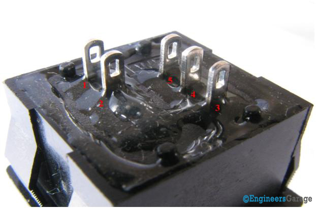
Fig. 2: Pin Out Terminals On Rear End Of Capacitive Touch Sensor
Pin out Terminals: Pin out terminals was visible onflipping it. These terminals are made from brass. The two separated terminals marked 1 & 2 are the LED terminals which glows on touching the sensor.The rest 3, 4& 5 are the supply voltage, ground and output terminals respectively.
Lock, Frame and Actuator

Fig. 3: Diagrammatical Image Showing Various Parts of A Capacitive Touch Sensor
Mechanical Lock and Scales: Mechanical locks are provided on the sides so that is can fit perfectly inside the water purifiers, kitchen appliances, vending machines and switches. Scales helps the device to adjust it height when housing in the aforesaid applications.
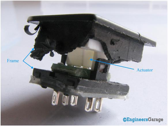
Fig. 4: Image Showing Frame and Actuator In A Capacitive Touch Sensor
Frame & Actuator:Cutting down the frame in to two parts we saw the actuator. Mechanical locking between the actuator and frames helps it to remain intact.
Wire Connections and PCB
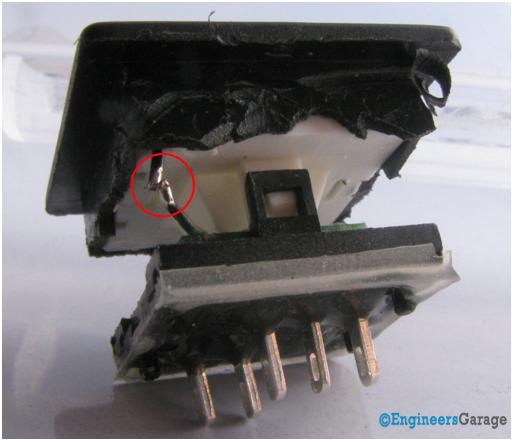
Fig. 5: Image Showing Closer View of Metal Connection In A Capacitive Touch Sensor
Metal Wire Connection: A metal wire connection comes down from the actuator to the PCB.Let us dig more to find out why this metal wire is used.
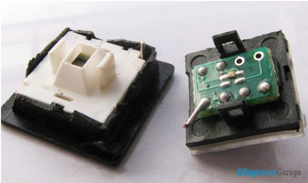
Fig. 6: Printed Circuit Board Present Inside A Capacitive Touch Sensor
Printed Circuit Board: After cutting down the sensor into two halves the clear view of the PCB can be seen. Printed Circuit Board has various components soldered onto it. Metal wire is also soldered on the PCB.
The LED is connected in the middle of the PCB connected with their respective terminals.
Fluorescent Plate and Electrode
White fluorescent plate: The white colored fluorescent plate is enclosed inside the glass surface. Light coming from the LED passes from the actuator and then it is reflected by the Fluorescent plate onto the glass surface. Reflected light helps in illuminating the markings (if written) on the glass surface.Glass surface is also used as a protective covering.
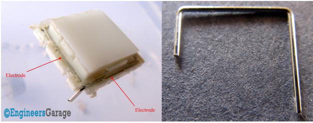
Fig. 7: Image Showing White Fluorescent Plate (Left) and Electrode (Right)
Electrode: A metal wire also known as electrode surrounds the fluorescent plate shown in the image above.Electrode is the heart of this device because itsenses the change in capacitance and carries this change in form of signal down to the PCB. Presence of iron in human body works as a sting of capacitors aligned to the surface of the body. When such strings of capacitors come in proximity with glass surface, a capacitance that is essentially coupled to ground is created, which causes a change in the measured capacitance determining the touch.
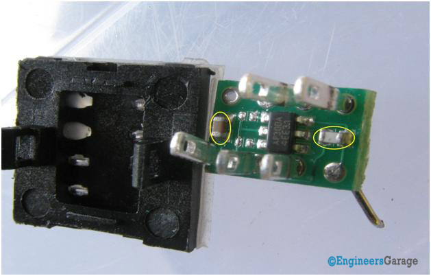
Fig. 8: Image Showing Closer Look Of Capacitive Touch Sensor PCB
Working of PCB: On plucking the PCB from its casing various components soldered on it can be seen.Touch Sensor IC is placed at the center of the PCB. Touch sensor IC senses the change in capacitance with the help of two reference ceramic capacitors connected through it encircled in the image. Ceramic capacitor helps in analyzing the change in capacitance.Sensor electrode is also connected to the ICthrough ceramic capacitor.When user touches the glass this touch sensation is carried in the form of signal by the electrode to the IC.Varying capacitance creates a frequency change in the sensor oscillator circuit. This frequency change is read by a system oscillator circuit which interacts with the touch detection circuit. Touch detection circuit accurately determines the input from the system oscillator circuit and gives the output.
Filed Under: Insight


Questions related to this article?
👉Ask and discuss on Electro-Tech-Online.com and EDAboard.com forums.
Tell Us What You Think!!
You must be logged in to post a comment.