Engineers Garage

  • Projects and Tutorials
    • Circuit Design
    • Electronic Projects
      • 8051
      • Arduino
      • ARM
      • AVR
      • PIC
      • Raspberry pi
      • STM32
    • Tutorials
    • Components
  • Articles
    • Tech Articles
    • Insight
    • Invention Stories
    • How to
    • What Is
  • News
    • EE Design News
    • DIY Reviews
    • Guest Post
    • Sponsored Content
  • Forums
    • EDABoard.com
    • Electro-Tech-Online
    • EG Forum Archive
  • Digi-Key Store
    • Cables, Wires
    • Connectors, Interconnect
    • Discrete
    • Electromechanical
    • Embedded Computers
    • Enclosures, Hardware, Office
    • Integrated Circuits (ICs)
    • Isolators
    • LED/Optoelectronics
    • Passive
    • Power, Circuit Protection
    • Programmers
    • RF, Wireless
    • Semiconductors
    • Sensors, Transducers
    • Test Products
    • Tools
  • EE Resources
    • DesignFast
    • LEAP Awards
    • Oscilloscope Product Finder
    • Video
    • White Papers
    • Webinars
  • EE Learning Center
  • Women in Engineering

Insight – How Head Phone TRS Connector or Jack works

June 24, 2013 By Ashutosh Bhatt


 Ever wondered how are wires connected to a connector. How different number of wires are connected to segments of the connector? A connector aka jack for the earphone, headphone, microphone, like any other gadgets has an equally interesting chapter in the book s of engineering. It is among the cheapest part but not the technically inferior. It deserves its attention from the engineers for its design and quality. The connector plays an important part of tranferring signals from the device like mobile, laptops, music players etc to the earphone and the microphone and vice versa. Even a small problem may lead to an unplesant experience with the device.
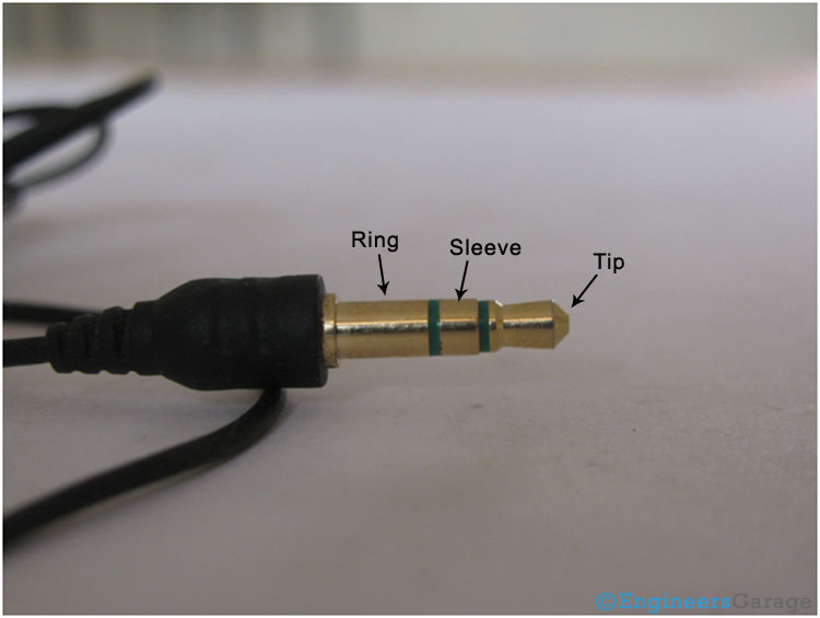
Image Showing Various Parts of A Typical Head Phone Jack
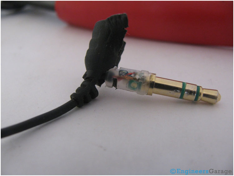
Fig.1 : Image Showing Various Parts of A Typical Head Phone Jack

The connector/jack shown in the above image is used for the earphone. This connector has three contacts/segments/parts called the TIP, RING, and the Sleeve as shown in the image. Therefore it is also called the TRS connector. These connectors are generally classified by the diameter. The above image shows a 3.5mm connector commonly used for the earphone or the headphone. Other commonly used jacks are avialble in 2.5mm and 6.35mm sizes.  
If a connector has four contacts it is called TRRS (TIP, RING, RING, SLEEVE) connector and if it has ony two contacts it is called as TS (TIP, SLEEVE) connector. TRRS connector is generally used with the earphones of a mobile phone or the ipods. The fourth contact is generally used for transferring the video signal or the output of the microphone. The TS connector is used with the microphone or the mic.

TRS Connector Inner View After Removal of Rubber Casing

Fig. 2: TRS Connector Inner View After Removal of Rubber Casing

Removing the rubber casing, we can see the wires connected to the connector. They are enclosed in a hard plastic cover to avoid any damage to the connections of the wire while handling the connector.

Picture Showing Various Wires Present In TRS Connector

Fig. 3:Picture Showing Various WIres Present In TRS Connector
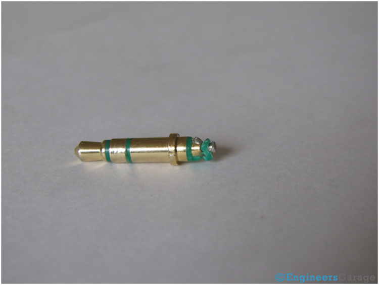
In a TRS connector there are three wires, one for the ground and the other two for the left and the right earpiece. Each earpiece has two wires one is ground and the other is the signal wire which carries the signal. The wire connected to TIP is for the left earpiece. The one connected to the RING if for the right earpiece and sleeve behaves as the ground.
TRS Connector Structure
Fig. 4: TRS Connector Structure
 
The above image shows the structure of the connector. There are three metallic parts of the connector and each one is insulated from the other by means of an insulating plastic which is green in color. The color may differ from manufacturer to manufacturer.
 
The structure of the connector is quite interesting. It has a thin rod at the center followed by an insulating plastic layer. Above the plastic layer is the hollow metallic pipe in the form of a cylinder. A large portion of the length of the pipe has a small diameter and a smaller segment towards the bottom has a larger diameter.  The wider portion of this pipe forms the ring of the jack. The narrow part is covered with the second insulating layer.  Above the second insulating plastic player is the third metallic pipe again cylindrical in shape and with a uniform diameter. This is the sleeve of the connector. The shape will become clearer in the subsequent images.

Image Showing Arrangement of Metallic Contacts in A TRS Connector
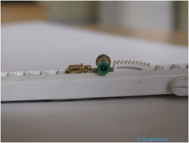
Fig. 5: Image Showing Arrangement of Metallic Contacts in A TRS Connector

The image above shows a closer look at the arrangement of the three metallic contacts.  The points where wires are soldered are also visible. 

Bottom Part of TRS Connector

Fig. 6: Bottom Part of TRS Connector
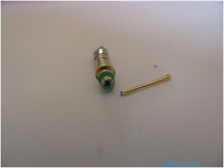
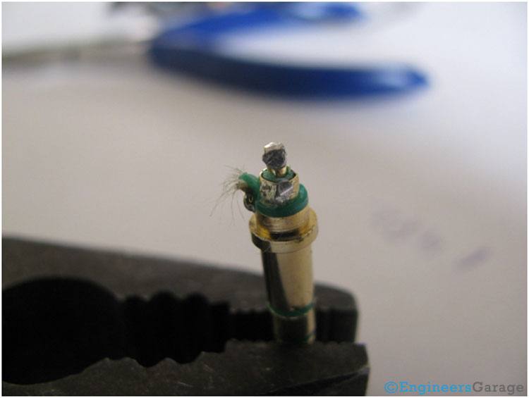
The bottom most part which is the tip of the connector is shown in the image above. It is removable and is connected to the center most rod from inside. The rod is also visible in the image which is surrounded by the green colored insulating plastic.
 
Innermost Metal Rod Present In TRS Connector
Fig. 7: Innermost Metal Rod Present In TRS Connector
 
The innermost rod of metal which acts as the tip of the connector is shown in the image above. An insulation covering of plastic is applied over it to prevent it from coming in direct electrical contact with the middle metallic contact.

Image Showing Shape of Middle Metallic Contact In A TRS Connector

Fig. 8: Image Showing Shape of Middle Metallic Contact In A TRS Connector

The shape of the middle metallic contact which forms the sleeve is shown in the image above. The green colored insulation covering can also be seen in the image.

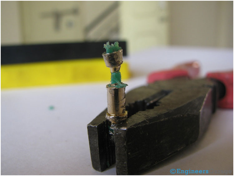
Image Showing Shape of Metallic Contact In TRS Connector

Fig. 9: Image Showing Shape of Metallic Contact In TRS Connector

This is the exact shape of the ring/the middle metallic contact/segment.


Related Articles Read More >

Insight – How an LED dot matrix display works
Insight – Learn the workings of a capacitive touch sensor
Insight – How Does an Odometer Work
Insight – How Expandable Screw Works

HAVE A QUESTION?

Have a technical question about an article or other engineering questions? Check out our engineering forums EDABoard.com and Electro-Tech-Online.com where you can get those questions asked and answered by your peers!


Featured Tutorials

  • Getting Started with the ESPlorer IDE
  • SENDING TEXT MESSAGE USING ESP8266
  • CONNECTION BETWEEN TWO ESP8266
  • ESP8266 WIFI HOTSPOT
  • HOME AUTOMATION USING ESP8266
  • Open WiFi Scanner using Esp8266

Stay Up To Date

Newsletter Signup

EE Training Center Classrooms

“ee

“ee

“ee

“ee

“ee

Recent Articles

  • What are the different types of fingerprint scanners?
  • TV remote hack using Arduino and IR sensor
  • Gesture sensor using Arduino
  • Diodes adds to its family of voltage-level shifters
  • Xilinx expands UltraScale+ portfolio to include compact, intelligent edge solutions

RSS EDABOARD.com Discussions

  • WiringPi SPI without Chip Select/Enable?
  • Need help in optimizing RF antenna balun on two port network analyzer
  • Different types of screened cable, which is best?
  • Radiated immunity testing for product that has an antenna and receiver?
  • ealtek RTL8722DM_mini Arduino Compatible WiFi + BLE IoT development board

RSS Electro-Tech-Online.com Discussions

  • Help with circuit design
  • Adjustable 0-5v ground switch
  • Multiple UART Hub to USB?
  • Need to add a question to a thread.
  • Weird switching transformer noise, Audio attached
Engineers Garage
  • Analog IC TIps
  • Connector Tips
  • DesignFast
  • EDABoard Forums
  • EE World Online
  • Electro-Tech-Online Forums
  • Microcontroller Tips
  • Power Electronic Tips
  • Sensor Tips
  • Test and Measurement Tips
  • 5G Technology World
  • About Us
  • Contact Us
  • Advertise

Copyright © 2021 WTWH Media LLC. All Rights Reserved. The material on this site may not be reproduced, distributed, transmitted, cached or otherwise used, except with the prior written permission of WTWH Media
Privacy Policy | Advertising | About Us

Search Engineers Garage

  • Projects and Tutorials
    • Circuit Design
    • Electronic Projects
      • 8051
      • Arduino
      • ARM
      • AVR
      • PIC
      • Raspberry pi
      • STM32
    • Tutorials
    • Components
  • Articles
    • Tech Articles
    • Insight
    • Invention Stories
    • How to
    • What Is
  • News
    • EE Design News
    • DIY Reviews
    • Guest Post
    • Sponsored Content
  • Forums
    • EDABoard.com
    • Electro-Tech-Online
    • EG Forum Archive
  • Digi-Key Store
    • Cables, Wires
    • Connectors, Interconnect
    • Discrete
    • Electromechanical
    • Embedded Computers
    • Enclosures, Hardware, Office
    • Integrated Circuits (ICs)
    • Isolators
    • LED/Optoelectronics
    • Passive
    • Power, Circuit Protection
    • Programmers
    • RF, Wireless
    • Semiconductors
    • Sensors, Transducers
    • Test Products
    • Tools
  • EE Resources
    • DesignFast
    • LEAP Awards
    • Oscilloscope Product Finder
    • Video
    • White Papers
    • Webinars
  • EE Learning Center
  • Women in Engineering