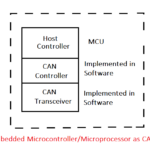
Engineers Garage

  • Electronics Projects and Tutorials
    • Electronic Projects
      • Arduino Projects
      • AVR
      • Raspberry pi
      • ESP8266
      • BeagleBone
      • 8051 Microcontroller
      • ARM
      • PIC Microcontroller
      • STM32
    • Tutorials
      • Audio Electronics
      • Battery Management
      • Brainwave
      • Electric Vehicles
      • EMI/EMC/RFI
      • Hardware Filters
      • IoT tutorials
      • Power Tutorials
      • Python
      • Sensors
      • USB
      • VHDL
    • Circuit Design
    • Project Videos
    • Components
  • Articles
    • Tech Articles
    • Insight
    • Invention Stories
    • How to
    • What Is
  • News
    • Electronic Product News
    • Business News
    • Company/Start-up News
    • DIY Reviews
    • Guest Post
  • Forums
    • EDABoard.com
    • Electro-Tech-Online
    • EG Forum Archive
  • DigiKey Store
    • Cables, Wires
    • Connectors, Interconnect
    • Discrete
    • Electromechanical
    • Embedded Computers
    • Enclosures, Hardware, Office
    • Integrated Circuits (ICs)
    • Isolators
    • LED/Optoelectronics
    • Passive
    • Power, Circuit Protection
    • Programmers
    • RF, Wireless
    • Semiconductors
    • Sensors, Transducers
    • Test Products
    • Tools
  • Learn
    • eBooks/Tech Tips
    • Design Guides
    • Learning Center
    • Tech Toolboxes
    • Webinars & Digital Events
  • Resources
    • Digital Issues
    • EE Training Days
    • LEAP Awards
    • Podcasts
    • Webinars / Digital Events
    • White Papers
    • Engineering Diversity & Inclusion
    • DesignFast
  • Guest Post Guidelines
  • Advertise
  • Subscribe

Intelligent Automated Home Lighting System

By Disha Karnataki September 8, 2024

Want to know why your monthly electricity bills are “so high”?  This is because when a person inside the room leaves the room hastily, he or she unknowingly leaves the  lights and fans switched on.
So, what’s next? The only way  to solve this is to use an Intelligent Automated Home Lighting System. In this system when a person enters the room the tube lights are switched on automatically and go off automatically when there is no body inside the room. This implies that the whole system is now at the tip of your motion.
Here we have used 8051 micro-controller along with two sensors.  These are IR Sensors or LED light falling on the LDR that act together to detect the motion inside the room  while microcontroller acts as a person counter and increments or decrements depending upon the number of people inside the room. If  the room is vacant then the  bulbs,  tube lights,  fans, etc switch off automatically on the exit of the last person who was  present there.

Block Diagram:

Overview of Automatic Light System for Home

Fig. 1: Overview of Automatic Light System for Home

Circuit Component Description

Before explaining the working let’s find out what are LDR Sensors:
• When the light level is less intense, resistance of the LDR is high
• But when light shines onto the LDR, resistance falls

Typical Image of Light Dependant Resistor

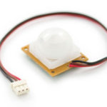
Fig. 2: Typical Image of Light Dependant Resistor

Block Diagram Explanation of each LDR working

Block Diagram representing working principle of LDR with Microcontroller

Fig. 3: Block Diagram representing working principle of LDR with Microcontroller

Block Diagram representing Microcontroller response to signals from LDR circuit

Fig. 4: Block Diagram representing Microcontroller response to signals from LDR circuit

Sensor Working

As properties are already stated

Case 1

When nobody interrupts the light falling on LDR:
The resistance of LDR is low and hence the base of the transistor does not get sufficient voltage to turn on the transistor and hence the collector voltage is almost equal to supply voltage that is 5V in this case.

Case 2 

When a person interrupts the light falling on LDR:
The resistance of LDR is high and hence transistor switches on and the collector voltage almost becomes equal to zero voltage.
These different collector voltages are picked by the microcontroller pins  which decide whether the person is going into the room or out of the room.
LDR sensor is just used for experimental purpose. In reality photo-transistor like the IR Sensors should be used because of good sensitivity.

Like this one:

Typical Image of IR Transmitter and Receiver

Fig. 5: Typical Image of IR Transmitter and Receiver

8051 Microcontroller Features

1)  8051 have 128 bytes of RAM
2)  8051 have 128 user defined flags
3)  It consists of 16 bit address bus
4)  It also consist of 3 internal and two external interrupts
5)  Less power usage in 8051 with respect to other micro-controller
6)  It consists of 16-bit program counter and data pointer
7)  8051 can process 1 million one-cycle instructions per second
8)  It also consist of 32 general purpose registers each of 8 bits
9)  ROM on 8051 is 4 Kbytes in size
10) It also consists of Two16 bit Timer/ Counter

Block Diagram of 8051 Microcontroller

Fig. 6: Block Diagram of 8051 Microcontroller

Fnd: There are two types in it:

Common Anode and Common Cathode
I have used common cathode in this project. So for display to be lit logic “1” has to be sent.

Final Image with all the Circuit Components

Image showing circuit for detecting entrance or exit of a visitor in action

Fig. 7: Image showing circuit for detecting entrance or exit of a visitor in action

Detection of Whether Person is Entering the Room or Person is Leaving the Room

Case 1:

When person  enters  the room- as the  person enters  the room  first  sensor1  is  interrupted  and  then  the  sensor 2

The  decoding  of these  two  signals  take  place  as follows:  if   a  first  low  is  sensed  due  to sensor-1  then, the  second low  sensed  by   microcontroller due to  sensor-2    will  indicate   that  person  is coming  inside  the  room  and  hence counter  will  increment  by  one  and  the  bulb  will be switched  on.

Case 2:

When  person  exits  the room –  he  will  interrupt  the  sensor2  and  then  will  interrupt  the  sensor-1.

The  decoding  of these  two  signals  take  place  as follows:  if   a  fist  low  is  sensed  due  to sensor-2  then, the  second low  sensed  by microcontroller due to  sensor-1 will  indicate   that  person  is  going  outside   the  room  and  hence counter will  decrement  by  one  and  the  bulb  will be switched  off  if  counter value  reaches  to zero.

Software and Project Overview

Software Overview

Flowchart of C Code used for Visitor Detection and Automatic Switching of lights

Fig. 8: Flowchart of C Code used for Visitor Detection and Automatic Switching of lights

Other Features that can be Included

1)  During day time as the person enters the room, the lights (bulb) should not automatically switch on
2)  If the person inside the room wants to intentionally inverse the state of the room, then  it can  be done by using remote control interfaced   with microcontroller.

Project Overview

Overview of working algorithm of Automatic Light System

Fig. 9: Overview of working algorithm of Automatic Light System 

You may also like:


  • What are top applications of CAN protocol?

  • How does LoRa modulation enable long-range communication?

  • What are the top tools for developing embedded software?

  • What are the top open-source software systems for home automation?

  • What is 3D scanning?

  • Motion detectors or motion sensors?

Project Source Code

###


CODE:IT  IS  WRITTEN  IN ASM  LANGUAGE:
org 0000h
ljmp main
org 0100h
main:mov p0,#00h    //make p0  as o/p port     BULB  IS CONNECTED HERE
mov p3,#0ffh       //make  p3  as i/p port        LDR  SENSORS ARE  CONNECTED HERE
mov p2,#00h      //make p2  as o/p port    FND  IS CONNECTED HERE
mov r0,#00h
mov p2,#0ffh
up:
lcall delay
lcall delay
lcall delay
lcall delay
lcall delay
lcall delay
f2:jb p3.0,f1          // CONTINUOUSLY  CHECK  FOR  A LOW  ON SENSOR-1  AND SENSOR-2 ALTERNATELY
lcall delay //
lcall delay                        //  DELAY  TO CAPTURE  THAT  EVENT PROPERLY
lcall delay                            //
lcall delay                         //
k2:jb p3.2,k2        //AFTER  LOW  OCCURRED  AT  SENSOR-1  THEN  CHECK  FOR  SENSOR-2  WHETHER  THE  PERSON  IS                               REALLY   ENTERING  THE  ROOM
lcall delay
lcall delay
lcall delay
lcall delay
lcall delay
inc r0
setb p0.0
lcall delay
lcall delay
lcall delay
sjmp fnd1         //DISPLAY    THE   INCREMENTED  VALUE  ON  FND
lcall delay
lcall delay
lcall delay
lcall delay
lcall delay
lcall delay
f1:jb p3.2,f2           //CONTINUOUSLY  CHECK  FOR  A LOW  ON SENSOR-1  AND SENSOR-2 ALTERNATELY
lcall delay             //
lcall delay       //                           DELAY  TO     CAPTURE  THE  EVENT
lcall delay            //
lcall delay                     //
lcall delay               //
k1:jb p3.0,k1         //AFTER  LOW  OCCURRED  AT  SENSOR-2  THEN  CHECK  FOR  SENSOR-1  WHETHER  THE  PERSON  IS                           REALLY   EXITING  THE  ROOM.
lcall delay
lcall delay
lcall delay
lcall delay
lcall delay
dec r0
lcall delay
lcall delay
lcall delay
lcall delay
lcall delay
lcall delay
ljmp fnd2                          //DISPLAY  THE  DECREMENTED  COUNT
c2:
cjne r0,#00h,j1
clr p0.0
ljmp up
j1:ljmp up
fnd1:
cjne r0,#01h,a1
mov p2,#0f9h
ljmp up
a1:cjne r0,#02h,a2
mov p2,#0a4h 
ljmp up
a2:cjne r0,#03h,a3
mov p2,#0b0h
ljmp up
a3:cjne r0,#04h,a4
mov p2,#19h 
ljmp up
a4:cjne r0,#05h,a5
mov p2,#92h
ljmp up
a5:cjne r0,#06h,a6
mov p2,#82h 
ljmp up
a6:cjne r0,#07h,a7
mov p2,#0f8h
ljmp up
a7:cjne r0,#08h,a8
mov p2,#00h 
ljmp up
a8:cjne r0,#09h,a9
mov p2,#10h 
a9:ljmp up
 
fnd2:
cjne r0,#00h,ac1
mov p2,#0ffh
ljmp c2
ac1:cjne r0,#01h,b1
mov p2,#0f9h
ljmp c2 
b1:cjne r0,#02h,b2
mov p2,#0a4h 
ljmp c2
b2:cjne r0,#03h,b3
mov p2,#0b0h
ljmp c2
b3:cjne r0,#04h,b4
mov p2,#19h 
ljmp c2
b4:cjne r0,#05h,b5
mov p2,#92h
ljmp c2
b5:cjne r0,#06h,b6
mov p2,#82h 
ljmp c2
b6:cjne r0,#07h,b7
mov p2,#0f8h
ljmp c2
b7:cjne r0,#08h,b8
mov p2,#00h 
ljmp c2
b8:cjne r0,#09h,b9
mov p2,#10h
ljmp c2 
b9:ljmp c2
delay:mov r2,#128
up1:mov r1,#0ffh
here:djnz r1,here
djnz r2,up1
ret
end


###


Circuit Diagrams

Circuit-Diagram-8051-Microcontroller-Based-Automatic-Lights

Project Video


Filed Under: Electronic Projects
Tagged With: 8051, Home Lighting System, microcontroller
 

Next Article

← Previous Article
Next Article →

Questions related to this article?
👉Ask and discuss on EDAboard.com and Electro-Tech-Online.com forums.


Tell Us What You Think!! Cancel reply

You must be logged in to post a comment.

EE TECH TOOLBOX

“ee
Tech Toolbox: Internet of Things
Explore practical strategies for minimizing attack surfaces, managing memory efficiently, and securing firmware. Download now to ensure your IoT implementations remain secure, efficient, and future-ready.

EE Learning Center

EE Learning Center
“engineers
EXPAND YOUR KNOWLEDGE AND STAY CONNECTED
Get the latest info on technologies, tools and strategies for EE professionals.

HAVE A QUESTION?

Have a technical question about an article or other engineering questions? Check out our engineering forums EDABoard.com and Electro-Tech-Online.com where you can get those questions asked and answered by your peers!


RSS EDABOARD.com Discussions

  • 12VAC to 12VDC 5A on 250ft 12AWG
  • Lightbox circuit help
  • Engineer's own PCB layout software guide?
  • LVS Mismatch Error in Simple Layout
  • Does mobility carrier ratio changes with Wn? (0.18um) inverter design

RSS Electro-Tech-Online.com Discussions

  • How to repair this plug in connector where wires came loose
  • Lightbox circuit
  • Fuel Auto Shutoff
  • Kawai KDP 80 Electronic Piano Dead
  • Python help with keystroke entries

Featured – Designing of Audio Amplifiers part 9 series

  • Basics of Audio Amplifier – 1/9
  • Designing 250 Milli Watt Audio Power Amplifier – 2/9
  • Designing 1 Watt Audio Power Amplifier – 3/9
  • Designing a Bass Boost Amplifier – 4/9
  • Designing a 6 Watt Car Audio Amplifier – 5/9
  • Design a low power amplifier for headphones- 6/9

Recent Articles

  • ITG Electronics releases gate drive transformers with 200 – 450 V DC capability
  • Stackpole introduces HCJ jumpers with 70.7 amp continuous current capability
  • Infineon releases MCU with 128K flash and multi-sense capabilities
  • ST introduces 600V GaN gate drivers with 300 ns start-up time
  • ABLIC releases S-19116 automotive voltage detector with 6.8μs response time

EE ENGINEERING TRAINING DAYS

engineering

Submit a Guest Post

submit a guest post
Engineers Garage
  • Analog IC TIps
  • Connector Tips
  • Battery Power Tips
  • DesignFast
  • EDABoard Forums
  • EE World Online
  • Electro-Tech-Online Forums
  • EV Engineering
  • Microcontroller Tips
  • Power Electronic Tips
  • Sensor Tips
  • Test and Measurement Tips
  • 5G Technology World
  • Subscribe to our newsletter
  • About Us
  • Contact Us
  • Advertise

Copyright © 2025 WTWH Media LLC. All Rights Reserved. The material on this site may not be reproduced, distributed, transmitted, cached or otherwise used, except with the prior written permission of WTWH Media
Privacy Policy

Search Engineers Garage

  • Electronics Projects and Tutorials
    • Electronic Projects
      • Arduino Projects
      • AVR
      • Raspberry pi
      • ESP8266
      • BeagleBone
      • 8051 Microcontroller
      • ARM
      • PIC Microcontroller
      • STM32
    • Tutorials
      • Audio Electronics
      • Battery Management
      • Brainwave
      • Electric Vehicles
      • EMI/EMC/RFI
      • Hardware Filters
      • IoT tutorials
      • Power Tutorials
      • Python
      • Sensors
      • USB
      • VHDL
    • Circuit Design
    • Project Videos
    • Components
  • Articles
    • Tech Articles
    • Insight
    • Invention Stories
    • How to
    • What Is
  • News
    • Electronic Product News
    • Business News
    • Company/Start-up News
    • DIY Reviews
    • Guest Post
  • Forums
    • EDABoard.com
    • Electro-Tech-Online
    • EG Forum Archive
  • DigiKey Store
    • Cables, Wires
    • Connectors, Interconnect
    • Discrete
    • Electromechanical
    • Embedded Computers
    • Enclosures, Hardware, Office
    • Integrated Circuits (ICs)
    • Isolators
    • LED/Optoelectronics
    • Passive
    • Power, Circuit Protection
    • Programmers
    • RF, Wireless
    • Semiconductors
    • Sensors, Transducers
    • Test Products
    • Tools
  • Learn
    • eBooks/Tech Tips
    • Design Guides
    • Learning Center
    • Tech Toolboxes
    • Webinars & Digital Events
  • Resources
    • Digital Issues
    • EE Training Days
    • LEAP Awards
    • Podcasts
    • Webinars / Digital Events
    • White Papers
    • Engineering Diversity & Inclusion
    • DesignFast
  • Guest Post Guidelines
  • Advertise
  • Subscribe