Requirements:
- AT89S52 (8051 microcontroller by ATMEL Corp.)
- ADXL-335 (or any 3- axis accelerometer )
- 16X2 alphanumeric LCD
- ADC0804 (8 bit analog to digital converter IC)
- 555 timer (for providing clock frequency to ADC)
- 11.0592MH
- 7805 voltage regulator IC

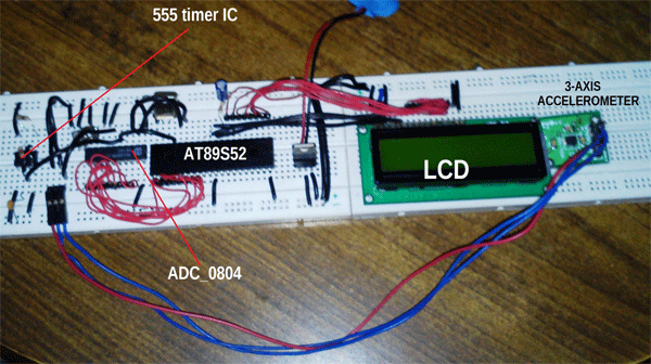
Fig. 1: Prototype of 8051 Microcontroller interfacing with ADXL335 Accelerometer Module
This project involves various stuffs like accelerometer module, 8 bit ADC, 555 timer IC, LCD display etc. So I’ll be discussing about all of them step by step.
ADXL 335 Accelerometer IC
First let’s talk about the Accelerometer IC; here I have used ADXL_335 which is a 3-axis accelerometer module. This module provides X, Y and Z axis data.

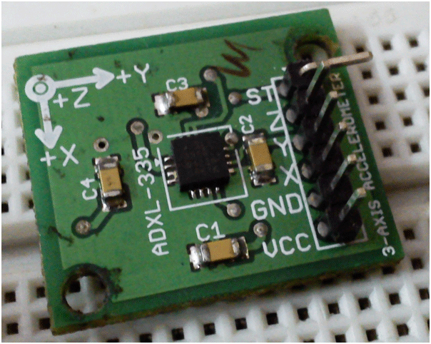
Fig. 2: Image of ADXL335 Accelerometer Module
It’s very easy to deal with such kind of modules as they just need the VCC and GND supply to get started, rest it is its job to provide us the analog data.
These modules work on simple concept like that of force acting on an object at inclined plane. It deals with the Mg(sin?) and Mg(cos?) part of the force and calculate the angle ? for further calculations. Now it also notices the change in force from which acceleration will be calculated.
These accelerometers do not respond to linear movements they respond to accelerated motions at very small scale.
Looking at the above picture you’ll notice that there is a ST pin. This pin deals with the value of ‘g’ (accelerations due to gravity) to be taken while calculating the result. Checkout its data sheet for more information. It will also work on a default value if you do not connect this pin anywhere.
ADC 0804
Now let’s talk about ADC_0804. I have used his IC to convert my analog data from ADXL_335 into a digital output. This was really necessary because microcontrollers only understand digital data.
Since this ADC is an 8 bit one, it will provide me 256 different digital values (0-255).
555 Timer IC
When coming on its working part, these ICs need a clock frequency to work on. Now I have used a 555 timer in a-stable mode but it can also be operated using its internal clock by just providing it an R-C circuit across it. This IC works properly on 640 KHz, so for 555 timer users do select the resistors and capacitor accordingly.
But how do we get to know about its functioning unless it is displayed somewhere. Therefore I have used a 16X2 LCD display to display the digital values on it. This will help us to see the values which correspond to different inclinations.
Now briefing about the circuit:
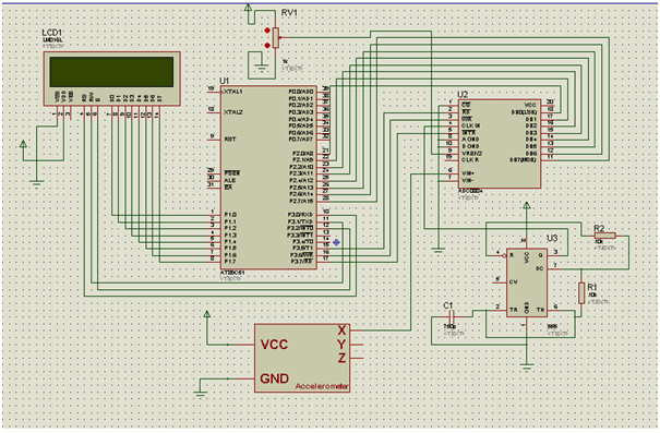
ADC’s data pins are connected to PORT 2 while its RD, WR and INT pins are connected to pin P3^5, 6 and 7 of the microcontroller respectively.
The resistor and capacitor values dealing with 555 are: R1=10K, R2=10K and C=750pF.
LCD is connected to PORT 1 with its RS, RW and E pin with pin P3^0, 1 and 2 respectively.
I have used a preset to provide a Vref/2 (2.5 V) at pin 9 of ADC.
I have also used two user defined header files: <delay.h> and <lcd.h>
Project Source Code
### #include<reg51.h> #include<delay.h> #include<lcd.h> sbit R=P3^5; sbit WD=P3^6; sbit INT=P3^7; int read_ADC() { int temp; R=1; WD=0; WD=1; while(INT==1); R=1; R=0; temp=P2; return temp; } void main() { unsigned char value='#'; INT=1; P2=0xff; Lcd8_Init(); while(1) { value=read_ADC(); Lcd8_Cmd(0x80); Lcd8_Num(value); Lcd8_Write_Char(' '); } } LCD.h: #include<string.h> //LCD Module Connections sbit RS=P3^0; sbit RW=P3^1; sbit E=P3^2; //End LCD Module Connections char *string; void delay(unsigned int time) { unsigned int a,b; for(a=0;a<=time;a++) for(b=0;b<=128;b++); } //LCD 8 Bit Interfacing Functions void Lcd8_Cmd(unsigned char value) { P1=value; RS=0; RW=0; E=1; delay(1); E=0; } void Lcd8_Init() { Lcd8_Cmd(0x38); //function set Lcd8_Cmd(0x0C); //display on,cursor off,blink off Lcd8_Cmd(0x01); //clear display Lcd8_Cmd(0x06); //entry mode, set increment } void Lcd8_Write_Char(unsigned char value) { P1=value; RS=1; RW=0; E=1; delay(1); E=0; } void Lcd8_Write_String(char *a) { int i; string=a; for(i=0;a[i]!='�';i++) Lcd8_Write_Char(a[i]); } void Lcd8_Num(unsigned int i) { unsigned char c; int num[10],p,k=0; if(i==0) Lcd8_Write_Char('0'); else { while(i>0) { num[k]=i%10; i=i/10; k++; } k--; for (p=k;p>=0;p--) { c=num[p]+48; P1 = c; RW = 0; RS = 1; E = 1; delay_msec(1); E = 0; } } } Delay.h: void delay_msec(int time) { int i=0; while(i<time) { TMOD=0x10; TH1=0xfc; TL1=0x66; TR1=1; while(TF1==0); TR1=0; TF1=0; i++; } } ###
Circuit Diagrams
Project Video
Filed Under: Electronic Projects
Filed Under: Electronic Projects


Questions related to this article?
👉Ask and discuss on EDAboard.com and Electro-Tech-Online.com forums.
Tell Us What You Think!!
You must be logged in to post a comment.