Engineers Garage

  • Electronic Projects & Tutorials
    • Electronic Projects
      • Arduino Projects
      • AVR
      • Raspberry pi
      • ESP8266
      • BeagleBone
      • 8051 Microcontroller
      • ARM
      • PIC Microcontroller
      • STM32
    • Tutorials
      • Audio Electronics
      • Battery Management
      • Brainwave
      • Electric Vehicles
      • EMI/EMC/RFI
      • Hardware Filters
      • IoT tutorials
      • Power Tutorials
      • Python
      • Sensors
      • USB
      • VHDL
    • Circuit Design
    • Project Videos
    • Components
  • Articles
    • Tech Articles
    • Insight
    • Invention Stories
    • How to
    • What Is
  • News
    • Electronic Product News
    • Business News
    • Company/Start-up News
    • DIY Reviews
    • Guest Post
  • Forums
    • EDABoard.com
    • Electro-Tech-Online
    • EG Forum Archive
  • DigiKey Store
    • Cables, Wires
    • Connectors, Interconnect
    • Discrete
    • Electromechanical
    • Embedded Computers
    • Enclosures, Hardware, Office
    • Integrated Circuits (ICs)
    • Isolators
    • LED/Optoelectronics
    • Passive
    • Power, Circuit Protection
    • Programmers
    • RF, Wireless
    • Semiconductors
    • Sensors, Transducers
    • Test Products
    • Tools
  • Learn
    • eBooks/Tech Tips
    • Design Guides
    • Learning Center
    • Tech Toolboxes
    • Webinars & Digital Events
  • Resources
    • Digital Issues
    • EE Training Days
    • LEAP Awards
    • Podcasts
    • Webinars / Digital Events
    • White Papers
    • Engineering Diversity & Inclusion
    • DesignFast
  • Guest Post Guidelines
  • Advertise
  • Subscribe

Interfacing 4026 with 7 segment display

By Ashutosh Bhatt June 14, 2013

CD4026 is a Johnson counter IC commonly used in digital display. It has a 5 stage Johnson decade counter with a decoder which converts the Johnson code to a 7 segment decoded output. To put it simply, it will convert the input into numeric display and can be seen on 7 segment display or with LED. It can be used for displaying analogue value such as temperature with pic microcontroller or for counting objects. There is various other applications like in 7 segment decimal display circuit, in clocks, timer etc. Advantages of 4026 counter are: It contains counters and 7 segment decoded in one package, It can be easily interfaced with 7 segment types, Ideal for low power display, Operated at wide range of temperature from 5V to 20V and the biggest advantage of the 4026B counter IC is that it can drive a 7-segment display without needing a decoder driver IC.


To understand the working of interfacing CD4026 with 7 segment display first we need to understand its pin diagram.
Now let us understand the working of individual pins-

Pin Diagram Of 4026 IC

Fig. 2: Pin Diagram Of 4026 IC 

 
1. Pin 1 or clock pin- It receives clock signals and at every positive clock, counter advances one by one. You can provide clock with the switch, 555 timer or with the help of logic gates. In short high pulse on this input increments the counter.
2. Pin 2 or disable clock (clk inhibit) pin- 4026 counter advances one by one by receiving positive pulse at this time clock inhibit pin should be grounded. If it is connected to supply than counter advancement will be inhibited means there will be no meaning of clock pulse. 
3. Pin 3 or enable display (En in) pin- It enable the 7 segment display to display the numeric value. It should be kept high for enabling the display. Mean output goes high when only when display enable is high.
4. Pin 4 or enable out- It Enables the carry out pin. In our circuit we have left this pin unconnected.
5. Pin 5 or divide by 10 output- It is used to complete one cycle for every 10 clock input cycle and it is also used to cascade more IC’s. 
6.Pin 6, pin7 and Pin9 to pin 13 – These are 7 decoded output from a to g used to illuminates the corresponding segment of 7 segment display to display the digit from 0 to 9.
7. Pin 14 or not 2 output (UNGATED “C” SEGMENT) signals- They are not gated by the Display clock and therefore are available continuously. This feature is a required in implementation of certain divider function such a as divide by 60 and divide by 12.
8. Pin 15 or Reset pin- It is used to reset the counter. When it receives high it clears the counter and counting again starts from zero. One important thing about reset pin that it should be again made low to start the counter once again. 
9. Pin 8 or ground pin and Pin 16 or Vdd – It should be connected to power supply.
To understand its working assemble the circuit as shown in circuit diagram 1-
It uses a 4026 combined counter and display driver IC which is designed to drive 7 segment displays. When you press the switch, counter starts from zero and it advances one each time whenever pin 1 receives a positive pulse. When you press the switch for first time numeric 1 will display, on pressing the switch again numeric 2 will display, giving you second output. In similar manner 3 and 4 will display. And when count reaches to 9, after that it will again starts it counting from zero.
For resetting the counter to zero, pin 15 must be taken high and then taken low again.  The table shown below shows sequence, how each segment glows after receiving clock signals?

Image Of Output From 4026 Counter

Fig. 3: Image Of Output From 4026 Counter

CMOS IC can switch millions of time in a second. This may cause the switch to deliver several pulses in rapid succession. But we just want one clock pulse at a time. Therefore we have used resistor with switches which create a short delay. Hence when we press switch it will provide high to pin 1 and hold it until switch is again press.
In circuit diagram 2 we have provide the facility to restart the counting from zero from any point as required by the user. This can be done, just by pressing the Switch S2 momentarily and with the help of Switch S3 you can hold the state of counting. Like you want number 4 should be displayed on the switch S3, no matter how many times you press S1 ( Clk input) or S2 (Reset) counter will not start neither it will reset.


Circuit Diagrams

Circuit-Diagram-Interfacing-4026-7-segment-display
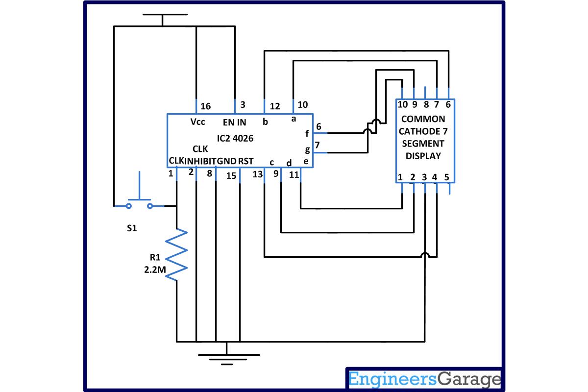
Circuit-Diagram-Interfacing-4026-7-segment-display_0
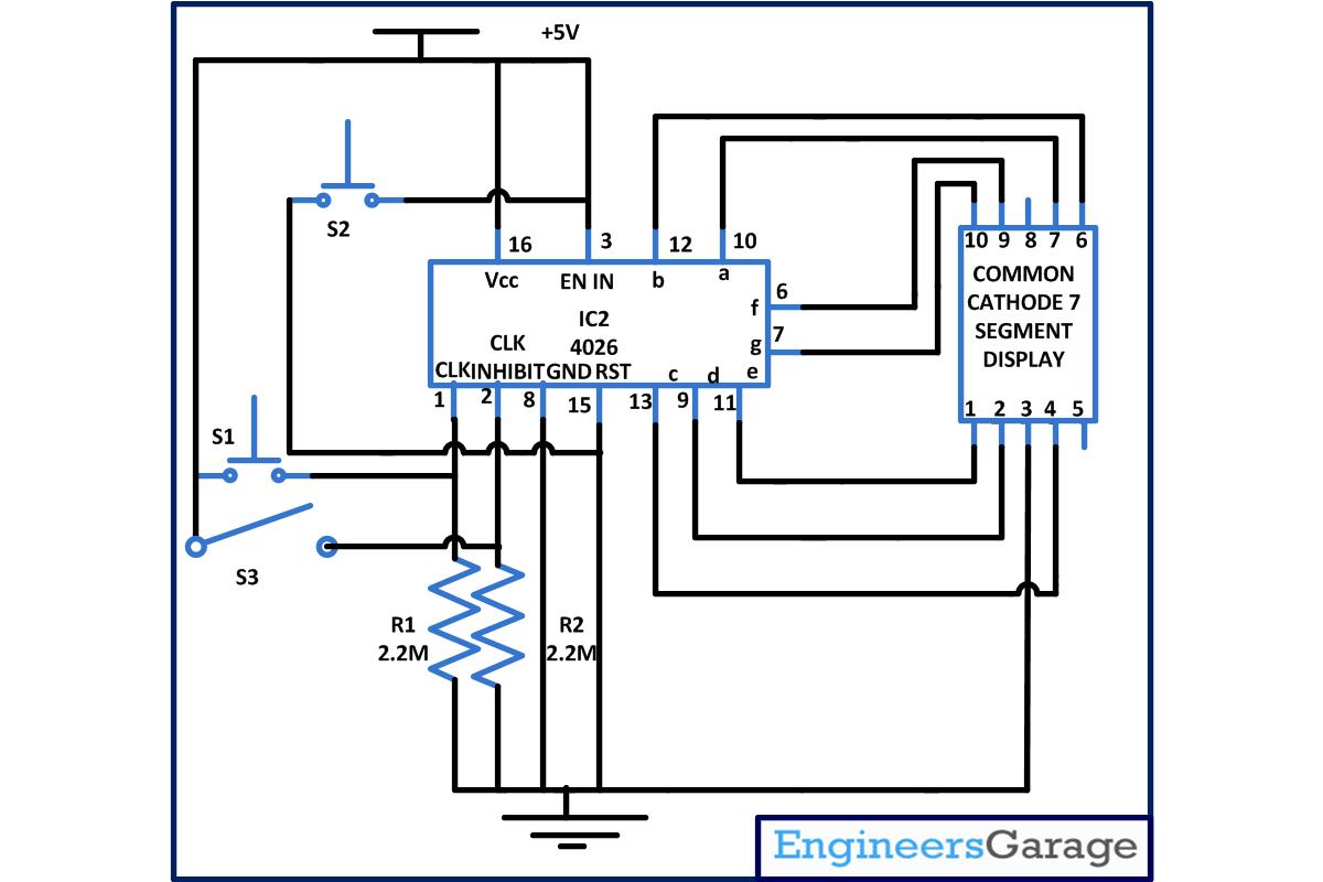
Project Components

  • Resistor
  • Seven Segment Display

Project Video


Filed Under: Electronic Projects
Tagged With: 4026, 7 segment display, circuit, interfacing
 

Next Article

← Previous Article
Next Article →

Questions related to this article?
👉Ask and discuss on Electro-Tech-Online.com and EDAboard.com forums.


Tell Us What You Think!! Cancel reply

You must be logged in to post a comment.

EE TECH TOOLBOX

“ee
Tech Toolbox: 5G Technology
This Tech Toolbox covers the basics of 5G technology plus a story about how engineers designed and built a prototype DSL router mostly from old cellphone parts. Download this first 5G/wired/wireless communications Tech Toolbox to learn more!

EE Learning Center

EE Learning Center
“engineers
EXPAND YOUR KNOWLEDGE AND STAY CONNECTED
Get the latest info on technologies, tools and strategies for EE professionals.

HAVE A QUESTION?

Have a technical question about an article or other engineering questions? Check out our engineering forums EDABoard.com and Electro-Tech-Online.com where you can get those questions asked and answered by your peers!


RSS EDABOARD.com Discussions

  • Snooping Around is All
  • mosfet driver problem in regeneration mode
  • Industrial Relay Board Design for Motorcycle Use
  • connector model question
  • ADEM III ECM — No CAN Signal & Power Supply Issue

RSS Electro-Tech-Online.com Discussions

  • Sump pit water alarm - Kicad 9
  • Pic18f25q10 osccon1 settings swordfish basic
  • Anyone jumped from Easyeda std to Easyeda pro?
  • turbo jet fan - feedback appreciated.
  • More fun with ws2812 this time XC8 and CLC

Featured – LoRa/LoRaWan Series

  • What is the LoRaWAN network and how does it work?
  • Understanding LoRa architecture: nodes, gateways, and servers
  • Revolutionizing RF: LoRa applications and advantages
  • How to build a LoRa gateway using Raspberry Pi
  • How LoRa enables long-range communication
  • How communication works between two LoRa end-node devices

Recent Articles

  • How IoT network topologies work
  • The top five AI startups to watch in 2025
  • STMicroelectronics unveils SoC based on secure MCU
  • Nexperia’s 48 V ESD diodes support higher data rates with ultra-low capacitance design
  • Taoglas releases Patriot antenna with 18 integrated elements covering 600 to 6000 MHz

EE ENGINEERING TRAINING DAYS

engineering

Submit a Guest Post

submit a guest post
Engineers Garage
  • Analog IC TIps
  • Connector Tips
  • Battery Power Tips
  • DesignFast
  • EDABoard Forums
  • EE World Online
  • Electro-Tech-Online Forums
  • EV Engineering
  • Microcontroller Tips
  • Power Electronic Tips
  • Sensor Tips
  • Test and Measurement Tips
  • 5G Technology World
  • Subscribe to our newsletter
  • About Us
  • Contact Us
  • Advertise

Copyright © 2025 WTWH Media LLC. All Rights Reserved. The material on this site may not be reproduced, distributed, transmitted, cached or otherwise used, except with the prior written permission of WTWH Media
Privacy Policy

Search Engineers Garage

  • Electronic Projects & Tutorials
    • Electronic Projects
      • Arduino Projects
      • AVR
      • Raspberry pi
      • ESP8266
      • BeagleBone
      • 8051 Microcontroller
      • ARM
      • PIC Microcontroller
      • STM32
    • Tutorials
      • Audio Electronics
      • Battery Management
      • Brainwave
      • Electric Vehicles
      • EMI/EMC/RFI
      • Hardware Filters
      • IoT tutorials
      • Power Tutorials
      • Python
      • Sensors
      • USB
      • VHDL
    • Circuit Design
    • Project Videos
    • Components
  • Articles
    • Tech Articles
    • Insight
    • Invention Stories
    • How to
    • What Is
  • News
    • Electronic Product News
    • Business News
    • Company/Start-up News
    • DIY Reviews
    • Guest Post
  • Forums
    • EDABoard.com
    • Electro-Tech-Online
    • EG Forum Archive
  • DigiKey Store
    • Cables, Wires
    • Connectors, Interconnect
    • Discrete
    • Electromechanical
    • Embedded Computers
    • Enclosures, Hardware, Office
    • Integrated Circuits (ICs)
    • Isolators
    • LED/Optoelectronics
    • Passive
    • Power, Circuit Protection
    • Programmers
    • RF, Wireless
    • Semiconductors
    • Sensors, Transducers
    • Test Products
    • Tools
  • Learn
    • eBooks/Tech Tips
    • Design Guides
    • Learning Center
    • Tech Toolboxes
    • Webinars & Digital Events
  • Resources
    • Digital Issues
    • EE Training Days
    • LEAP Awards
    • Podcasts
    • Webinars / Digital Events
    • White Papers
    • Engineering Diversity & Inclusion
    • DesignFast
  • Guest Post Guidelines
  • Advertise
  • Subscribe