For this project, except for a GPS-enabled mobile phone to record GPS NMEA sentences, no hardware is required. I used an Android phone, and several applications are available in the Play Store which will allow you to record NMEA sentences either in the “.txt” or in the “.log” format. Since not all users have access to an Android phone, I have attached two sets of GPS sentences to allow you to complete this project. Since no GPS signal could be obtained indoors, the first set of GPS sentences were recorded by walking for approximately 100 metres outdoors. The second set of GPS sentences were recorded indoors for a no GPS signal condition. The only other hardware that is needed is a Host PC. For this project, I used a HP Pavilion G6 series laptop with an Intel 2.1GHz processor and 3 GB RAM running Windows 7 Home Basic 64-bit OS. The following software is needed to complete this project successfully:
1) GPS Sim
2) Labcenter Proteus v7.6 or upwards (for this project, v7.8 with SP2 was used)
3) Eltima Serial Port Splitter v5.0
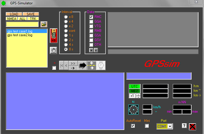
Fig.1 : GPS Simulator window
Figure 1 shows the GPS Simulator window. To begin browsing to the folder which has the NMEA sentence log files, click on the browse button. Select the interval as 8 seconds. 4 seconds can also be selected; however, any interval lower than this will cause errors in Proteus and latitude and longitude information will not be viewed for every sentence. Also, select RMC as the sentence type, as only these sentences are passed to the Proteus simulation and are used to obtain latitude and longitude information. Next, select the COM1 port in the port selection menu. Any available port can be selected as long as it is not the COM2 port. The COM2 port is used in Proteus to transmit data to the controller’s USART RX pin. Also the port selected from this menu has to be the same port that is used to create a virtual link (using Eltima Serial Splitter) between the port and the COM2 port in Proteus. The GPS Simulator software can be downloaded from the following link: http://www.lichtenheld-mch.de/gpssim.htm
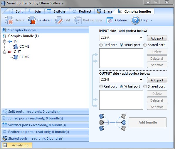
Fig. 2:Serial Splitter window
Figure 2 shows the window for Serial Splitter 5.0 by Eltima Software. To create the virtual link between the port selected in GPS Simulator and the COM2 port used in Proteus, select the ‘Complex Bundles’ tab. For the input side, select the ‘Virtual port’ option and then the COM port used by GPS Simulator to pass the sentences to Proteus (COM1 in this case). Then click the ‘Add port’ button. Repeat the same procedure for the output side, but select the COM2 port. Once both, input and output ports have been added, click on the ‘Add bundle’ button. A successfully created bundle will show up in the left side of the software’s window as shown in the figure. A 14-day trial version of Serial Splitter can be downloaded from the following link: http://www.eltima.com
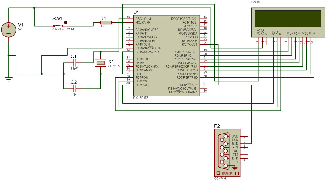
Circuit diagram tab shows the Proteus circuit for the simulation. A 15.9744 MHz crystal is connected across pins 13 and 14 of the PIC18F458 microcontroller. Switch SW1 is the reset switch. The RXD pin of the P2 COMPIM component is connected to the RX pin (pin 26) of the controller. A MAX232 IC is not required as it is built into the COMPIM component. Port D of the controller is connected to the parallel data lines D0:D7 of the LCD display. Pins VSS and VDD of the LCD are grounded and supplied a voltage of 5V respectively. The RS, R/W and E pins of the LCD are connected to pins 38, 39 and 40 respectively on Port B.
To develop the control logic for parsing GPS sentences, the UART module was configured and latitude and longitude information was parsed using string manipulation. To configure the UART module, the RX pin was set for input and serial reception was enabled by assigning a value of 0x90 to the RCSTA receive register. The baud rate generator register SPBRG was assigned a value of 0x19 for 9600bps baud rate. Asynchronous mode was chosen by clearing the SYNC bit in the TXSTA transmit status and control register. The receive flag was cleared and data was copied from the receive register RCREG to a temporary variable when the flag set upon reception of data. The continuous receive enable bit CREN in the RCSTA receive register was then cleared to allow for continuous reception of data.
$GPRMC sentences were passed from the GPS simulator to the controller’s RX pin via the COMPIM component. Two sets of these sentences were pre-recorded using a GPS-enabled mobile phone for two conditions – a changing GPS location and no GPS signal. For a changing GPS location, the first set of sentences was recorded over a 100m distance. For no GPS signal, the second set of GPS sentences was recorded indoors. The $GPRMC and $GPGGA sentences (GPS signal found condition) had the same length (76 characters). If no GPS signal was found, sentences which had a length less than 76 characters did not contain latitude and longitude information, instead a series of commas were found in the recorded sentences. These characteristics of the recorded sentences were used to identify the $GPRMC sentence and then extract latitude and longitude information. Identification of the $GPRMC sentence and the no GPS signal was achieved using string comparison. Once the GPS signal and the $GPRMC were found, the latitude and longitude were extracted by determining the starting position and number of characters in the latitude and longitude values. Figure 5 shows the control logic for parsing the $GPRMC sentence.
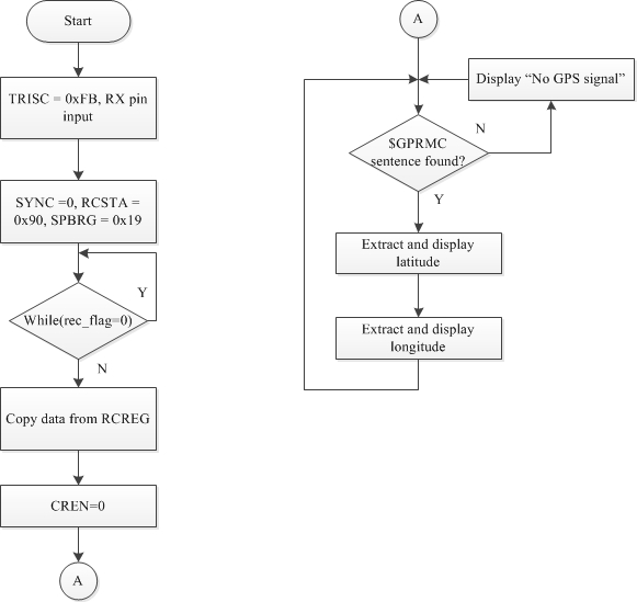
Fig. 3: Control logic for parsing GPS sentence
To run the simulation the following steps should be performed in the order indicated:
1) Launch Serial Splitter and create the complex bundle between the in port of GPS Simulator and COM2 port of Proteus circuit
2) Open ‘gps.DSN’ in Proteus
3) Launch GPS Simulator and select the log file
4) Start the simulation in Proteus and then begin transmission of the log file in GPS Simulator
The LCD display will show that the GPS signal is found and display latitude and longitude information. Only part of this information is shown in Figure 6, as the LCD display is cleared and then following information on latitude and longitude is shown. For the second log file, the LCD display will show that the GPS signal is not found.
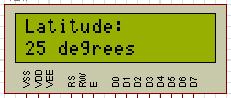
Fig. 6 :Latitude information shown partly
Project Source Code
###
#include#include#pragma config OSC=HS#pragma config OSCS=OFF#pragma config WDT=OFF#pragma config DEBUG=OFF#pragma config LVP=OFF#define rs PORTBbits.RB7#define rw PORTBbits.RB6#define en PORTBbits.RB5#define lcd PORTDvoid mydelay(unsigned char);void data_wrt(unsigned char);void init_lcd(void);void cmd_wrt(unsigned char);void lat_long(void);void nothing(void);unsigned char cmd[]={0x38,0x01,0x0C,0x06}; //LCD commandunsigned char strcompare(char *s1, char *s2, unsigned char size); //String compare functionunsigned char gps[77]={'�'};unsigned char status;signed char ret;/**/unsigned char lati[11] = "Latitude: ";unsigned char longi[12] = "Longitude: ";unsigned char deg[9] = " degrees";unsigned char mins[10] = "minutes, ";void main(void){//check for sentence variablesstatic unsigned char gprmc[7], gprmctemp[7]="$GPRMC";static int gp1,gp2; static int st=0,len=6;static int i,j,k;//check for satellite fix variablesstatic unsigned char sc[2], sctemp[2]="V";static int sc1,sc2; static int sc_st=8,sc_len=1;static unsigned char nogps[14] = "No GPS signal";static unsigned char yesgps[17] = "GPS signal found";int x,y;status = 0;ret = 0;TRISB = 0x00; //make portB as outputTRISD = 0x00; //make portD as outputPORTCbits.RX = 1; //Set RX pin as inputTXSTAbits.SYNC = 0; //asynchronous modeTXSTAbits.BRGH = 1; //high baud rateRCSTA = 0x90; //enables serial port and receiverSPBRG = 0x19; //9600 baud rate, 16MHz xtalinit_lcd();mydelay(1);cmd_wrt(0x80);//force cursor at the begining of 1st linewhile(1){for(x=0;x<76;x++){while(PIR1bits.RCIF==0); //wait to receivegps[x] = RCREG;}//Check if $GPRMC sentence receivedfor (gp1=st,gp2=0; gp2gprmc[gp2]=gps[gp1];gprmc[gp2]='�';for (sc1=sc_st,sc2=0; sc2sc[sc2]=gps[sc1];sc[sc2]='�';if (strcompare(gprmc,gprmctemp,6)==1 && (strcompare(sc,sctemp,1)==0))//Check if GPS signal found{//cmd_wrt(0x80);for(j=0;j<16;j++)data_wrt(yesgps[j]);mydelay(500);cmd_wrt(0xC0);mydelay(1);cmd_wrt(0x80);mydelay(1);lat_long();}if ((strcompare(gprmc,gprmctemp,6)==1) && (strcompare(sc,sctemp,1)==1)){//cmd_wrt(0x80);for(i=0;i<13;i++)data_wrt(nogps[i]);mydelay(500);cmd_wrt(0x01);mydelay(1);cmd_wrt(0x80);mydelay(1);}RCSTAbits.CREN=0; //Clear continuous receive enable bitRCSTAbits.CREN=1; //Set continuous receive enable bit for continuous reception}}void lat_long(void){static unsigned char latitude[13], longitude[14];static int lat_a,lat_b,long_c,long_d; static int lat_st1=19,long_st2=33,lat_len1=13,long_len2=14;/****Latitude****///Declarations for separating digits and characterstatic int lat1_a,lat2_b,lat1_c,lat2_d; static int la_st1=0,la_st2=11,la_len1=12,la_len2=1;static unsigned char latF1[12], latF2[1];//Declarations for separating degrees and minutes from digitsstatic int laa,lab,lac,lad; static int last1=0,last2=1,lalen1=2,lalen2=9;static unsigned char latFinal1[2], latFinal2[9];//Variables for displaystatic int i1,j1,k1,l1,m1,n1;/****Longitude****///Declarations for separating digits and characterstatic int long1_a,long2_b,long1_c,long2_d; static int long_st1=0,lo_st2=12,long_len1=12,lo_len2=1;static unsigned char longF1[12], longF2[1];//Declarations for separating degrees and mintues from digitsstatic int loa,lob,loc,lod; static int lost1=0,lost2=2,lolen1=2,lolen2=9;static unsigned char longFinal1[3], longFinal2[9];static int i2,j2,k2,l2,m2,n2;/*latitude*///Extracting latitude informationfor (lat_a=lat_st1,lat_b=0; lat_blatitude[lat_b]=gps[lat_a];latitude[lat_b]='�';//Separating digits and characterfor (lat1_a=la_st1,lat2_b=0; lat2_blatF1[lat2_b]=latitude[lat1_a];latF1[lat2_b]='�';for (lat1_c=la_st2,lat2_d=0; lat2_dlatF2[lat2_d]=latitude[lat1_c];latF2[lat2_d]='�';//Viewing in degrees and minutesfor (laa=last1,lab=0; lablatFinal1[lab]=latF1[laa];latFinal1[lab]='�';for (lac=last2,lad=0; ladlatFinal2[lad]=latF1[lac];latFinal2[lad]='�';/*put code for displaying latitude here*/cmd_wrt(0x01);mydelay(1);cmd_wrt(0x80);for(i1=0;i1<10;i1++)data_wrt(lati[i1]);mydelay(50);cmd_wrt(0xC0);mydelay(1);for(j1=0;j1<2;j1++)data_wrt(latFinal1[j1]);for(k1=0;k1<8;k1++)data_wrt(deg[k1]);mydelay(500);cmd_wrt(0x01);mydelay(1);cmd_wrt(0x80);for(l1=0;l1<9;l1++)data_wrt(latFinal2[l1]);cmd_wrt(0xC0);for(m1=0;m1<9;m1++)data_wrt(mins[m1]);mydelay(1);for(n1=0;n1<1;n1++)data_wrt(latF2[n1]);mydelay(500);/*longitude*/cmd_wrt(0x01);mydelay(1);cmd_wrt(0x80);for(i2=0;i2<10;i2++)data_wrt(longi[i2]);mydelay(50);cmd_wrt(0xC0);mydelay(1);//Extracting longitude informationfor (long_c=long_st2,long_d=0; long_dlongitude[long_d]=gps[long_c];longitude[long_d]='�';//Separating digits and characterfor (long1_a=long_st1,long2_b=0; long2_blongF1[long2_b]=longitude[long1_a];longF1[long2_b]='�';for (long1_c=lo_st2,long2_d=0; long2_dlongF2[long2_d]=longitude[long1_c];longF2[long2_d]='�';//Viewing in degrees and minutesfor (loa=lost1,lob=0; loblongFinal1[lob]=longF1[loa];longFinal1[lob]='�';for (loc=lost2,lod=0; lodlongFinal2[lod]=longF1[loc];longFinal1[lod]='�';/*put code for displaying longitude here*/for(j2=0;j2<3;j2++)data_wrt(longFinal1[j2]);for(k2=0;k2<8;k2++)data_wrt(deg[k2]);mydelay(500);cmd_wrt(0x01);mydelay(1);cmd_wrt(0x80);for(l2=0;l2<9;l2++)data_wrt(longFinal2[l2]);cmd_wrt(0xC0);for(m2=0;m2<9;m2++)data_wrt(mins[m2]);mydelay(1);for(n2=0;n2<1;n2++)data_wrt(longF2[n2]);mydelay(500);cmd_wrt(0x01);mydelay(1);cmd_wrt(0x80);mydelay(1);RCSTAbits.CREN=0; //Clear continuous receive enable bitRCSTAbits.CREN=1; //Set continuous receive enable bit for continuous receptionmain();}unsigned char strcompare(char *s1, char *s2, unsigned char size){unsigned char i;for(i=0;i{if(*s1 != *s2){return 0;}else{//Do nothing}s1++;s2++;}return 1;}/*****LCD Code*****/void init_lcd(){int j;for(j=0;j<4;j++)cmd_wrt(cmd[j]);}/***********************************/void cmd_wrt(unsigned char cmddata){rs=0;// select rs as command regrw=0;// to write into lcdlcd=cmddata;en=1;mydelay(1);en=0;mydelay(1);}void data_wrt(unsigned char datat){rs=1;// select rs as data regrw=0;lcd=datat;en=1;mydelay(1);en=0;mydelay(1);}void mydelay(unsigned char val){for(;val>=1;val--){Delay1KTCYx(1);}}###
Circuit Diagrams
Filed Under: Electronic Projects

Questions related to this article?
👉Ask and discuss on EDAboard.com and Electro-Tech-Online.com forums.
Tell Us What You Think!!
You must be logged in to post a comment.