Stm32 Buzzer Alarm – Project functionality
Stm32 Buzzer Project main skill development
Piezo Buzzer with Stm32 microcontroller – Main Project
I write a getting started with stm32f103c8t6 development board tutorial and you can find it by clicking the below button. Button will lead you to a tutorial which explains about the board and how to configure and program it using stm32cubemx software utility.
- How to configure the GPIO pins of stm32 microcontroller in stm32cubemx code configurator and how to import the code in keil uvison arm ide.
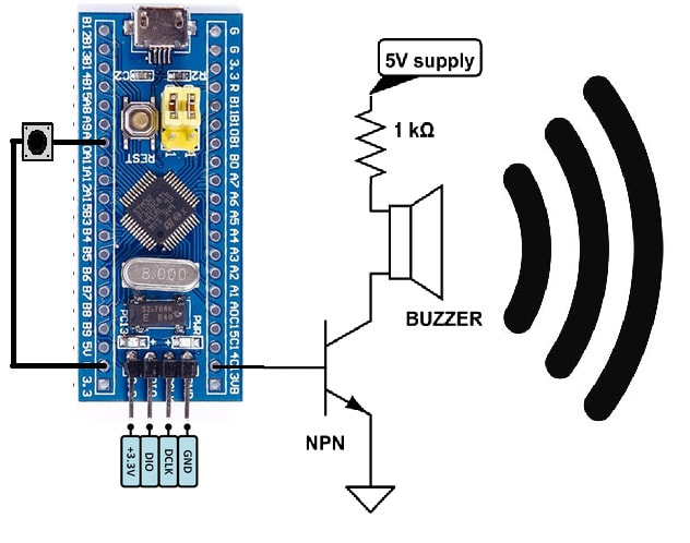
Stm32 Piezo Buzzer – Project Circuit
Why i used transistor in the circuit?
Well stm32 microcontrollers are 3.3 volt tolerant devices. Their GPIO’s can output max voltage of 3.3 v and source about 20 mA to 40 mA of current at 3.3 volts. This voltage and current is not suitable for driving a piezo buzzer. Small piezo buzzers operates on 3-5v and consumes about 15 mA of current. Average piezo buzzers works on about 5 volts and consumes 50 mA of current. So its a bad idea to directly drive a piezo sound buzzer with stm32 microcontroller or any general purpose microprocessor GPIO pin.
Transistor on the other hand operates on a very small voltage and have the ability to drive heavy loads which are not possible to drive directly with GPIO’s of microcontrollers. To prevent stm32 microcontroller from any power related issues like power on reset and other potential errors buzzer is interfaced with transistor. Now transistor controls the buzzer and transistor is controlled by stm32 microcontroller.
An NPN transistor is used in the project. Buzzer is connected to collector side of the npn transistor with a 1 k ohm resistor. Resistor limits the current drained by buzzer and only lets the needed amount by buzzer to flow in the circuit.
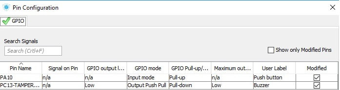
Pull up and pull down resistors activation
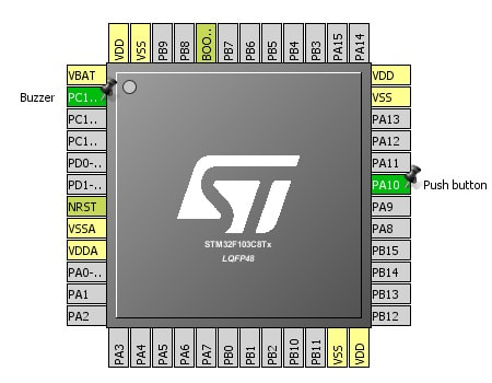
I activated resistors associated with each pin i used in the project. Push button is used as input. I activated its pull up resistor. One end of push button is connected to stm32 Port-A pin#10 and the other end is grounded. Pull up resistor is activated to normally make the input high. Now when ever the user presses the push button the input state changes from 5 volts to 0 volts and microcontroller will accept it as voltage transition and we can do our stuff when transition is recognized. I don’t want the input pin to be floating so i activated the pull up resistor. In code you can understand it easily. I will also explain it in code. Our input pin now behaves like the system below.

Buzzer with stm32 microcontroller – Project code
if(HAL_GPIO_ReadPin(Push_button_GPIO_Port, Push_button_Pin)==GPIO_PIN_RESET)
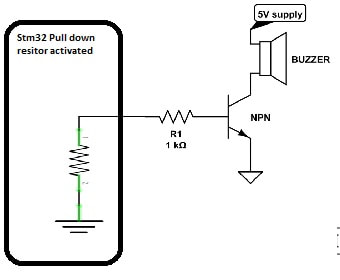
If button pressed then make the Port-C pin#13 high. Normally port-c pin#13 is low due to pull down resistor activation. When the stm32 pin is made high it sources 3 volts out. Which ultimately makes the base of transistor high and transistor channel activates making buzzer to produce sound.
HAL_GPIO_WritePin(Buzzer_GPIO_Port, Buzzer_Pin,GPIO_PIN_SET);
If no press remain low.
HAL_GPIO_WritePin(Buzzer_GPIO_Port, Buzzer_Pin,GPIO_PIN_RESET);
Future Work:
You can design an alarm using buzzer and clock with stm32 microcontroller. A security system involving buzzer and other actuators will be a nice project to take one step a head from this buzzer with stm32 getting started tutorial.
Filed Under: Microcontroller Projects, STM32.

Questions related to this article?
👉Ask and discuss on EDAboard.com and Electro-Tech-Online.com forums.
Tell Us What You Think!!
You must be logged in to post a comment.