Engineers Garage

  • Electronic Projects & Tutorials
    • Electronic Projects
      • Arduino Projects
      • AVR
      • Raspberry pi
      • ESP8266
      • BeagleBone
      • 8051 Microcontroller
      • ARM
      • PIC Microcontroller
      • STM32
    • Tutorials
      • Sensor Series
      • 3D Printing
      • AI
      • ARDUINO Compatible Coding
      • Audio Electronics
      • Battery Management
      • Beginners Electronics Series
      • Brainwave
      • Digital electronics (DE)
      • Electric Vehicles
      • EMI/EMC/RFI
      • EVs
      • Hardware Filters
      • IoT tutorials
      • LoRa/LoRaWAN
      • Power Tutorials
      • Protocol
      • Python
      • RPI Python Programming
      • Sensors
      • USB
      • Thermal management
      • Verilog
      • VHDL
    • Circuit Design
    • Project Videos
    • Components
  • Articles
    • Tech Articles
    • Insight
    • Invention Stories
    • How to
    • What Is
  • News
    • Electronic Product News
    • Business News
    • Company/Start-up News
    • DIY Reviews
    • Guest Post
  • Forums
    • EDABoard.com
    • Electro-Tech-Online
    • EG Forum Archive
  • DigiKey Store
    • Cables, Wires
    • Connectors, Interconnect
    • Discrete
    • Electromechanical
    • Embedded Computers
    • Enclosures, Hardware, Office
    • Integrated Circuits (ICs)
    • Isolators
    • LED/Optoelectronics
    • Passive
    • Power, Circuit Protection
    • Programmers
    • RF, Wireless
    • Semiconductors
    • Sensors, Transducers
    • Test Products
    • Tools
  • Learn
    • eBooks/Tech Tips
    • Design Guides
    • Learning Center
    • Tech Toolboxes
    • Webinars & Digital Events
  • Resources
    • Digital Issues
    • EE Training Days
    • LEAP Awards
    • Podcasts
    • Webinars / Digital Events
    • White Papers
    • Engineering Diversity & Inclusion
  • Guest Post Guidelines
  • Advertise
  • Subscribe

Interfacing DS1307 with Atmega 16 AVR MCU

By Pankaj May 24, 2015

Aim of the project

The aim is to interface DS1307 RTC (a real time clock) IC with an Atmega16 microcontroller and display the time, day, and date on anLCD.


The general application of the circuit 

To display the current time like a watch does, it can even be used for time based home automation or industrial automation.  It can also work as a stop watch or an alarm.


Working  of the Circuit

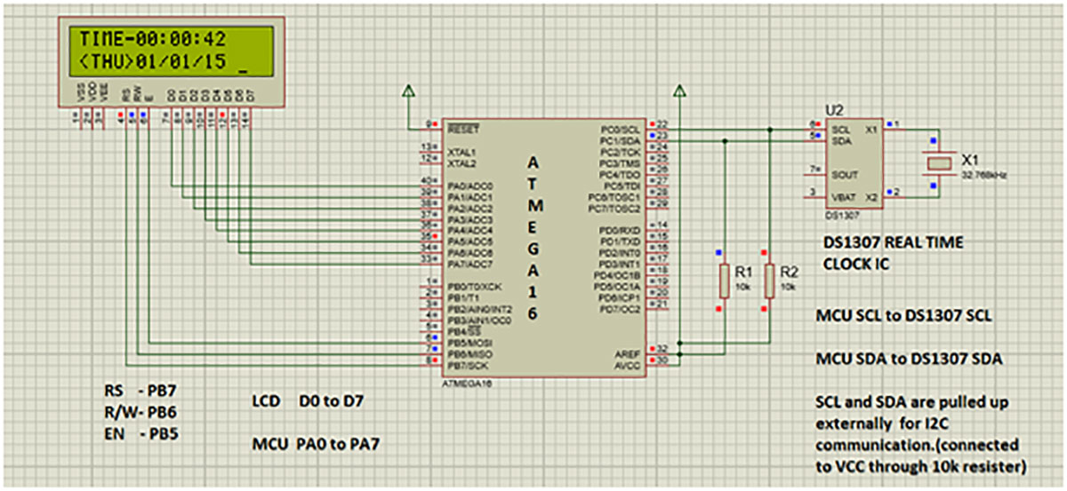
In this project mcu atmega16 communicates with DS1307 IC on I2C communication protocol, in which MCU works as master and DS1307 as a slave. I2C communication takes place through SDA(serial data) and SCL(serial clock line)  where Atmega16 and DS1307 are connected through  these lines. Atmega16 writes the data In registers of DS1307 and then reads it which is then displayed on the LCD.


Circuit Description

The circuit consists of Atmega16 MCU, DS1307 IC and 16/2 LCD. The microcontroller Atmega16 communicates to the DS1307 through the I2C serial data bus line SDA and serial clock line SCL.
 
The PC0 and PC1 pins of microcontroller apart from I/O operations also perform SCL and SDA functions respectively.
 
During I2C operations the SCL and SDA lines are pulled high externally (refer the circuit diagram). External pull up means connecting the line to VCC through a resistor.  Although the value of  resistor that I have used here is 10k ohm, 4.7k ohm or 5.6k ohm can also be used.
 

The LCD is connected to PORTA and PORTB of the Atmega16. The data pins D0 to D7 are connected to respective pins A0 to A7 of the Atmega16.The control pins RS, R/W and EN are connected to PB7,  PB6, PB5 pins of Atmega16 respectively.


ATMEGA16 MCU

Pin Diagram of AVR ATMega16

 Fig. 1: Pin Diagram of AVR ATMega16

ATmega16 is an 8-bit high performance microcontroller of Atmel’s Mega AVR family with low power consumption.  It is based on enhanced RISC (Reduced Instruction Set Computing, Know more about RISC and CISC Architecture) architecture with 131 powerful instructions. Most of the instructions are executed in one machine cycle. Atmega16 can work on a maximum frequency of 16MHz.
 It has 16 KB programmable flash memory, static RAM of 1 KB and EEPROM of 512 Bytes. The endurance cycle of flash memory and EEPROM is 10,000 and 100,000, respectively.
 
 
This is a 40 pin microcontroller. There are 32 I/O (input/output) lines which are divided into four 8-bit ports designated as PORTA, PORTB, PORTC and PORTD.
 
It has various in-built peripherals like USART, ADC, Analog Comparator, SPI, JTAG etc. Each I/O pin has an alternative task related to in-built peripherals. The following table shows the pin description of ATmega16.
 

DS1307 RTC REAL TIME CLOCK IC

Pin Diagram of DS1307 RTC IC

 Fig. 2: Pin Diagram of DS1307 RTC IC

-VBAT is to be supplied 3V through a 3V lithium cell.
 
-Crystal value used is 32.768kHz which is connected to X1 and X2.
 

I2C COMMUNICATION

I²C (Inter-Integrated Circuit), pronounced I-squared-C, is a multi-master, multi-slave, single-ended, serial computer bus invented by Philips Semiconductor, known today as NXP Semiconductors, used for attaching low-speed peripherals to computer motherboards and embedded systems. Alternatively I²C is spelled I2C (pronounced I-two-C) or IIC (pronounced I-I-C)
 
I²C uses only two bidirectional open-drain lines, Serial Data Line (SDA) and Serial Clock Line (SCL), pulled up with resistors. Typical voltages used are +5 V or +3.3 V although systems with other voltages are permitted.
 
The I²C reference design has a 7-bit or a 10-bit (depending on the device used) address space.[3] Common I²C bus speeds are the 100 kbit/s standard mode and the 10 kbit/s low-speed mode, but arbitrarily low clock frequencies are also allowed. Recent revisions of I²C can host more nodes and run at faster speeds (400 kbit/s Fast mode)
 
Note that the bit rates are quoted for the transactions between master and slave without clock stretching or other hardware overhead. Protocol overheads include a slave address and perhaps a register address within the slave device as well as per-byte ACK/NACK bits. Thus the actual transfer rate of user data is lower than those peak bit rates alone would imply. For example, if each interaction with a slave inefficiently allows only 1 byte of data to be transferred, the data rate will be less than half the peak bit rate.
 
The maximum number of nodes is limited by the address space, and also by the total bus capacitance of 400 pF, which restricts practical communication distances to a few meters.
 

16 BY 2 LCD –YJD1602A1

The LCD receives the data from Atmega16 and displays it in readable format.   Pin1 VSS is connected to GND, Pin2 VCC connected to 5V and  Pin3 VE is connected to a potentiometer to receive a contrast voltage b/w 0 and 5V.

RS, R/W,EN are connected to PB7,PB6,PB5 pins on the MCU and 8 data pins are connected to PORTA of MCU.

Typical Image of Character LCD Module

Fig. 3: Typical Image of Character LCD Module

Block Diagram-

Block Diagram of AVR ATMega16 and RTC DS1307 Interfacing Circuit

Fig. 4: Block Diagram of AVR ATMega16 and RTC DS1307 Interfacing Circuit

COMPONENTS  REQUIRED

1      ATEMGA16

Typical Image of AVR ATMega16 Microcontroller

Fig. 5: Typical Image of AVR ATMega16 Microcontroller

2      DS1307 

Typical Image of DS1307 RTC IC

 Fig. 6: Typical Image of DS1307 RTC IC

3      LCD 16 BY 2 YJD1602A1

CIRCUIT DIAGRAMTypical Image of 16X2 Character LCD

 Fig. 7: Typical Image of 16X2 Character LCD

(Check the circuit diagram tab for complete circuit for Interfacing ds1307 with atmega 16 avr mcu)

Prototype of AVR ATMega16 and RTC DS1307 Interfacing Circuit

Fig. 8: Prototype of AVR ATMega16 and RTC DS1307 Interfacing Circuit


Image of Character LCD displaying current time of the day

Fig. 9: Image of Character LCD displaying current time of the day

Project Source Code


#include <avr/io.h>

  #include <util/delay.h>

  #include <avr/interrupt.h>

  #include <stdlib.h>


  #define MT_SLA_ACK1             0x18        //twi interface commands for ds1307

  #define MT_DATA_ACK1         0x28


  #define START                              0x08

  #define MT_SLA_ACK               0x40

  #define MT_DATA_ACK           0x58


  #define SLA_R   0b11010001                             //address for ds1307

  #define SLA_W   0b11010000


uint8_tBCDToDecimal (uint8_t bcdByte)

  {

            return (((bcdByte& 0xF0) >> 4) * 10) + (bcdByte& 0x0F);

  }


uint8_tDecimalToBCD (uint8_t decimalByte)

  {

            return (((decimalByte / 10) << 4) | (decimalByte % 10));

  }


uint8_t address;


voidinitialize_LCD(void);


charfirst_column_positions_for_LCD[4]={0,64,20,84};


voidcheck_if_LCDisbusy(void);                    // checking LCD ready to process


voidLCD_enabledisplay(void);          //disply enable


voidsend_A_command(unsigned char command);         //  sending command


voidsend_A_character(unsigned char character);     // sending character


voidsend_A_string(char *stringsofcharacter);    // send string


voidgoto_location(uint8_t x, uint8_t y);


voidsend_string_and_location(uint8_t x,uint8_t y, char *stringOFcharacter);


voidsend_integer(uint8_t x,uint8_t y,intintegertodisplay,charnumberdigits);


uint8_t data_Read;


uint8_t H,M,S,WK,DY,MN,YR;


uint8_t H1,M1,S1,WK1,DY1,MN1,YR1;


voidTWI_bit_rate_set(void)

{

            TWBR=8;      // set  SCL frequency  to 400kHz

            TWCR|=1<<TWEN;

}


intTWI_start()

{

TWCR = (1<<TWINT)|(1<<TWSTA)|(1<<TWEN);      // set start


while (!(TWCR & (1<<TWINT)));      //Wait for TWINT Flag set. This indicates that the START condition has been transmitted


if ((TWSR & 0xF8) != START)         //Check value of TWI Status Register. Mask prescaler bits. If status different from START go to ERROR

return 0;


}


intTWI_send_address_read()                // READ..........send slave address in read mode

{


TWDR = SLA_R;

TWCR = (1<<TWINT) | (1<<TWEN);     // Load SLA_W into TWDR Register. Clear TWINT bit in TWCR to start transmission of address


while (!(TWCR & (1<<TWINT)));      //Wait for TWINT Flag set. This indicates that the SLA+W has been transmitted, and ACK/NACK has been received


if ((TWSR & 0xF8) != MT_SLA_ACK)    // Check value of TWI Status Register. Mask prescaler bits. If status different from MT_SLA_ACK go to ERROR

return 0;


}


intTWI_send_addr_data(uint8_t data)      // WRITE.........send the address of data

{


TWDR=data;

TWCR = (1<<TWINT) | (1<<TWEN);      //Load DATA into TWDR Register. Clear TWINT bit in TWCR to start transmission of data


while (!(TWCR & (1<<TWINT)));       // Wait for TWINT Flag set. This indicates that the DATA has been transmitted, and ACK/NACK has been received


if ((TWSR & 0xF8) != MT_DATA_ACK1)     //  Check value of TWI Status Register. Mask prescaler bits. If status different from MT_DATA_ACK go to ERROR

return 0;


}


intTWI_get_data()    // READ.....get the address of the data required

{

TWCR = (1<<TWINT) | (1<<TWEN);      //Load DATA into TWDR Register. Clear TWINT bit in TWCR to start transmission of data


while (!(TWCR & (1<<TWINT)));       // Wait for TWINT Flag set. This indicates that the DATA has been transmitted, and ACK/NACK has been received


data_Read=TWDR;

TWCR = (1<<TWINT) | (1<<TWEN);      //Load DATA into TWDR Register. Clear TWINT bit in TWCR to start transmission of data


while (!(TWCR & (1<<TWINT)));       // Wait for TWINT Flag set. This indicates that the DATA has been transmitted, and ACK/NACK has been received


if ((TWSR & 0xF8) != MT_DATA_ACK)     //  Check value of TWI Status Register. Mask prescaler bits. If status different from MT_DATA_ACK go to ERROR

return 0;


}


intTWI_send_address_write()                // WRITE........send slave address in write  mode

{


TWDR = SLA_W;

TWCR = (1<<TWINT) | (1<<TWEN);     // Load SLA_W into TWDR Register. Clear TWINT bit in TWCR to start transmission of address


while (!(TWCR & (1<<TWINT)));      //Wait for TWINT Flag set. This indicates that the SLA+W has been transmitted, and ACK/NACK has been received


if ((TWSR & 0xF8) != MT_SLA_ACK1)    // Check value of TWI Status Register. Mask prescaler bits. If status different from MT_SLA_ACK go to ERROR

return 0;


}


voidTWI_stop()    //................................stop................................................//

{


TWCR = (1<<TWINT)|(1<<TWEN)|(1<<TWSTO);   //  Transmit STOP condition


}


int write(uint8_t pg_addr,uint8_t data1)

{

TWI_bit_rate_set();


TWI_start();


TWI_send_address_write();


TWI_send_addr_data(pg_addr); // send address of page


TWI_send_addr_data(data1);  // send data to be written to the address


TWI_stop();    

}


int read(uint8_t pg_addr)

{

TWI_bit_rate_set();


TWI_start();


TWI_send_address_write();


TWI_send_addr_data(pg_addr);


TWI_start();


TWI_send_address_read();


TWI_get_data();


TWI_stop();    

}


voiddisplay_num(uint8_t DIG,uint8_t loc)

{

if(DIG<=9)

  {send_integer(loc,1,0,3);

send_integer((loc+1),1,DIG,3);

  }

else

send_integer(loc,1,DIG,3);


}


voiddisplay_ALP(uint8_t DIG,uint8_t loc)

{

if(DIG<=9)

  {send_integer(loc,2,0,3);

send_integer((loc+1),2,DIG,3);

  }

else

send_integer(loc,2,DIG,3);


}


voiddisplay_weekday(uint8_t WK)

{

if(WK==1){send_string_and_location(1,2,"<SUN>");}

else if(WK==2){send_string_and_location(1,2,"<MON>");}

else if(WK==3){send_string_and_location(1,2,"<TUE>");}

else if(WK==4){send_string_and_location(1,2,"<WED>");}

else if(WK==5){send_string_and_location(1,2,"<THU>");}

else if(WK==6){send_string_and_location(1,2,"<FRI>");}

else if(WK==7){send_string_and_location(1,2,"<SAT>");} 

}


#define sec_register                           0x00

#define min_register                         0x01

#define hour_register                                    0x02

#define weekday_weekend_register 0x03

#define day_register                          0x04

#define month_register                                 0x05

#define year_register                         0x06


voidRTC_write_data(void)

{


write(sec_register,DecimalToBCD(00));

write(min_register,DecimalToBCD(52));

write(hour_register,DecimalToBCD(20));

write(weekday_weekend_register,DecimalToBCD(1));

write(day_register,DecimalToBCD(15));

write(month_register,DecimalToBCD(03));

write(year_register,DecimalToBCD(15));


}


voidRTC_read_data()

{          

read(hour_register);

hour_digits(data_Read);


read(min_register);

min_digits(data_Read);


read(sec_register);

sec_digits(data_Read);


read(weekday_weekend_register);

weekday_weekend_digits(data_Read);


read(day_register);

day_digits(data_Read);


read(month_register);

month_digits(data_Read); 


read(year_register);

year_digits(data_Read);    


send_string_and_location(1,1,"TIME-");

display_num(H,6);

send_string_and_location(8,1,":");

display_num(M,9);

send_string_and_location(11,1,":");

display_num(S,12);


display_weekday(WK);


display_ALP(DY,6);

send_string_and_location(8,2,"/");

display_ALP(MN,9);

send_string_and_location(11,2,"/");

display_ALP(YR,12);


}


voidhour_digits(uint8_t data)

{H=BCDToDecimal(data);}


voidsec_digits(uint8_t data)

{S=BCDToDecimal(data);}      


voidmin_digits(uint8_t data)

{M=BCDToDecimal(data);}


voidweekday_weekend_digits(uint8_t data)

{WK=BCDToDecimal(data);}


voidday_digits(uint8_t data)

{DY=BCDToDecimal(data);}


voidmonth_digits(uint8_t data)

{MN=BCDToDecimal(data);}


voidyear_digits(uint8_t data)

{YR=BCDToDecimal(data);}


voidinitialize_LCD()

{

DDRB|=(1<<5)|(1<<6)|(1<<7);

_delay_ms(2);

send_A_character(0x01);

_delay_ms(2);

send_A_command(0x38);

_delay_us(10);

send_A_command(0b00001110);

_delay_us(10);


}


voidcheck_if_LCDisbusy()

{


DDRA=0;

PORTB|=1<<6;

PORTB&=~1<<6;


while(PORTA>=0x80)

{


LCD_enabledisplay();


}


DDRA=0xFF;


}


voidLCD_enabledisplay()

{

PORTB|=1<<5;  //   enable on , bit of delay then off

_delay_ms(5);

PORTB&=~1<<5;


}


voidsend_A_command(unsigned char command)

{


check_if_LCDisbusy();

PORTA=command;

PORTB&=~((1<<6)|(1<<7));  //  readwrite =0 and register select also =0 for sending a command

LCD_enabledisplay();

PORTA=0;


}


voidsend_A_character(unsigned char character)

{


check_if_LCDisbusy();                                                                                     // readwrite =0 and register select =1 for sending a command

PORTA=character;

PORTB&=~(1<<6);

PORTB|=1<<7;

LCD_enabledisplay();

DDRA=0;


}

voidsend_A_string(char *stringsofcharacter)

{


while(*stringsofcharacter>0)

{

            send_A_character(*stringsofcharacter++);

}


}


voidgoto_location(uint8_t x, uint8_t y)       // takes cursor to the desired position as on x and y value.

{

send_A_command(0x80 + first_column_positions_for_LCD[y-1]+ (x-1));


}


voidsend_string_and_location(uint8_t x,uint8_t y, char *stringofcharacters)  //   the string is taken to the desired location on lcd

{


goto_location(x,y);

send_A_string(stringofcharacters);

}


voidsend_integer(uint8_t x,uint8_t y,intintegertodisplay,charnumberdigits) // specify the no. of digits of the integer

{

charstringtodisplay[numberdigits];

itoa(integertodisplay,stringtodisplay,10);   // 10 means decimal -user undersatandable

            // converted the integer to string

            inti;

for(i=0;i<4;i++) {send_A_string(" ");} //reserves 4 digits for our display and removes any garbage

send_string_and_location(x,y,stringtodisplay);


send_A_string(" ");  // space provided to get rid of any garbage  or 0  value


}


void wait(int a)

{   inti;

            for(i=1;i<=a;i++)

            {_delay_ms(1000);}

}


int main(void)

{ 

            initialize_LCD();

send_A_command(0x01);


            RTC_write_data();

// first program with write statement then comment write statement and reprogram


            while(1)

            {

            RTC_read_data();

            }                      

}

###


Circuit Diagrams

Circuit-Diagram-AVR-ATMega16-RTC-DS1307-Interfacing-Prototype


Filed Under: Electronic Projects


Next Article

← Previous Article
Next Article →

Questions related to this article?
👉Ask and discuss on Electro-Tech-Online.com and EDAboard.com forums.


Tell Us What You Think!! Cancel reply

You must be logged in to post a comment.

Submit a Guest Post

submit a guest post

EE TECH TOOLBOX

“ee
Tech Toolbox: Power Efficiency
Discover proven strategies for power conversion, wide bandgap devices, and motor control — balancing performance, cost, and sustainability across industrial, automotive, and IoT systems.

EE Learning Center

EE Learning Center
“engineers
EXPAND YOUR KNOWLEDGE AND STAY CONNECTED
Get the latest info on technologies, tools and strategies for EE professionals.

HAVE A QUESTION?

Have a technical question about an article or other engineering questions? Check out our engineering forums EDABoard.com and Electro-Tech-Online.com where you can get those questions asked and answered by your peers!


RSS EDABOARD.com Discussions.

  • Can anyone please help me with this single board computer?
  • Anyone successfully communicated to the BlueNRG-M0 module on the B-L4S5I-IOT01A board
  • How to Build an Audio Tone Control?
  • Current version of LTspice not working on Windows 11?
  • Addressable Latch in My Logic Project

RSS Electro-Tech-Online.com Discussions

  • Measuring controller current output with a meter
  • KiCad custom symbol definition correct approach
  • restarting this Christmas project
  • Anyone In The US Ordered From AliExpress Recently?
  • My Advanced Realistic Humanoid Robots Project

Featured Tutorials

Real Time Hardware Filter Design

  • Practical implementation of bandpass and band reject filters
    Practical implementation of bandpass and band reject filters
  • Practical application of hardware filters with real-life examples
    Practical application of hardware filters with real-life examples
  • A filter design example
    A filter design example
  • Types of filter responses
    Types of filter responses
  • What are the two types of hardware filters?
    What are the two types of hardware filters?
  • What are hardware filters and their types?
    What are hardware filters and their types?
More Tutorials >

Recent Articles

  • Posifa sensors improve low-flow accuracy in compact systems
  • Acopian releases low-profile power supplies rated to 900 W
  • Octavo Systems OSDZU-3 REF Development Platform
  • Same Sky adds enclosure design to its audio engineering capabilities
  • Waterproof SMA-to-MHF I LK assemblies introduced by Amphenol RF

EE ENGINEERING TRAINING DAYS

engineering
Engineers Garage
  • Analog IC TIps
  • Connector Tips
  • Battery Power Tips
  • EDABoard Forums
  • EE World Online
  • Electro-Tech-Online Forums
  • EV Engineering
  • Microcontroller Tips
  • Power Electronic Tips
  • Sensor Tips
  • Test and Measurement Tips
  • 5G Technology World
  • Subscribe to our newsletter
  • About Us
  • Contact Us
  • Advertise

Copyright © 2025 WTWH Media LLC. All Rights Reserved. The material on this site may not be reproduced, distributed, transmitted, cached or otherwise used, except with the prior written permission of WTWH Media
Privacy Policy

Search Engineers Garage

  • Electronic Projects & Tutorials
    • Electronic Projects
      • Arduino Projects
      • AVR
      • Raspberry pi
      • ESP8266
      • BeagleBone
      • 8051 Microcontroller
      • ARM
      • PIC Microcontroller
      • STM32
    • Tutorials
      • Sensor Series
      • 3D Printing
      • AI
      • ARDUINO Compatible Coding
      • Audio Electronics
      • Battery Management
      • Beginners Electronics Series
      • Brainwave
      • Digital electronics (DE)
      • Electric Vehicles
      • EMI/EMC/RFI
      • EVs
      • Hardware Filters
      • IoT tutorials
      • LoRa/LoRaWAN
      • Power Tutorials
      • Protocol
      • Python
      • RPI Python Programming
      • Sensors
      • USB
      • Thermal management
      • Verilog
      • VHDL
    • Circuit Design
    • Project Videos
    • Components
  • Articles
    • Tech Articles
    • Insight
    • Invention Stories
    • How to
    • What Is
  • News
    • Electronic Product News
    • Business News
    • Company/Start-up News
    • DIY Reviews
    • Guest Post
  • Forums
    • EDABoard.com
    • Electro-Tech-Online
    • EG Forum Archive
  • DigiKey Store
    • Cables, Wires
    • Connectors, Interconnect
    • Discrete
    • Electromechanical
    • Embedded Computers
    • Enclosures, Hardware, Office
    • Integrated Circuits (ICs)
    • Isolators
    • LED/Optoelectronics
    • Passive
    • Power, Circuit Protection
    • Programmers
    • RF, Wireless
    • Semiconductors
    • Sensors, Transducers
    • Test Products
    • Tools
  • Learn
    • eBooks/Tech Tips
    • Design Guides
    • Learning Center
    • Tech Toolboxes
    • Webinars & Digital Events
  • Resources
    • Digital Issues
    • EE Training Days
    • LEAP Awards
    • Podcasts
    • Webinars / Digital Events
    • White Papers
    • Engineering Diversity & Inclusion
  • Guest Post Guidelines
  • Advertise
  • Subscribe