‘Flex Sensor’ or ‘Bend Sensor’ is the one that changes its resistance depending on the amount of bend on the sensor.
They convert the change in bend into electrical resistance – the more the bend, the more the resistance value.
These sensors are widely used in various applications such as – Automotive controls, Medical Devices, Fitness Products, Virtual Reality gaming consoles, Animatronics, Robotics, etc.

Fig. 1: Prototype of Arduino and Flex Sensor Interfacing
This tutorial aims to provide a detailed guide to flex sensor and its interfacing with Arduino.
The Flex sensor patented technology is based on resistive carbon elements. As a variable printed resistor, it achieves great form-factor on a thin flexible substrate. When the substrate is bent, the sensor produces a resistance output correlated to the bend radius – the smaller the radius, the higher the resistance value.
This is how a flex sensor looks like:

Fig. 2: Typical Image of Flex Sensor
They are usually in the form of a thin strip from 1”-5” long that vary in resistance range. Change in resistance with increasing bend is depicted in the snapshot below:

Fig. 3: Image showing working principle of Flex Sensor
In simple words, flex sensors are analog resistors which work as variable analog voltage dividers.

Fig. 4: Image showing construction of Flex Sensor
They contain carbon resistive elements within a thin flexible substrate. More carbon means less resistance.
Usually a flex sensor is used in voltage divider configuration. It is shown below:

Fig. 5: Image of Voltage Divider Network with Flex Sensor
Interfacing with Arduino
NOTE: Although the active portion of the sensor (the area between the black squares) is quite sturdy, its pin-end is susceptible to kinking and eventual failure. I recommend reinforcing or securing this area (for example, clamping or gluing down the sensor at the black square nearest to the pins) to ensure that it doesn’t flex along with the rest of the sensor.
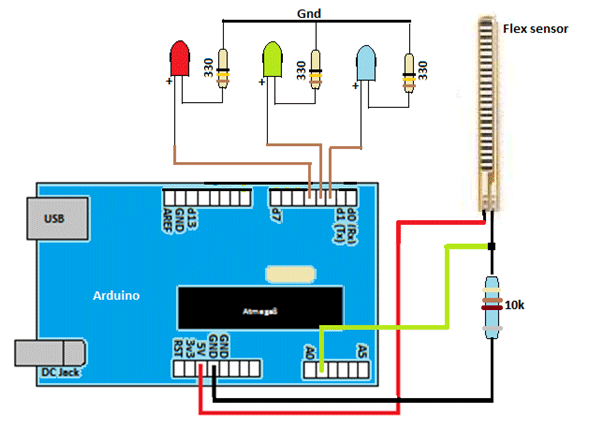
Make the connections of the flex sensor in voltage divider configuration as shown above. Take your Arduino and connect the divider point to Analog Input of the board.
The analogRead () function will provide the sensor values.
flex = analogRead (1);
Serial.print (flex);
This will print values on the serial monitor.
Now we’ll show you the amount of bend through LEDs. Connect the Red, Green and Blue LEDs to the Arduino Digital pins 4, 3 and 2 respectively, as shown in the circuit.
With no bend in the flex sensor, only Blue LED will glow whereas a small bend will turn on the Green LED.. On applying large amount of bend, Red LED will glow, while the remaining two LEDs will be turned OFF, indicating a large bend.

Fig. 6: Image showing red LED glowing on bending flex sensor hard

Fig. 7: Image showing green LED glowing on slightly bending flex sensor
Project Source Code
###


#define blue 2
#define green 3
#define red 4
unsigned int f;
void setup()
{
  pinMode(blue,OUTPUT);
  pinMode(green,OUTPUT);
  pinMode(red,OUTPUT);
  Serial.begin(9600);
}
void loop()
{
  f=analogRead(1);
  Serial.println(f);
  if(f>300)                          //No Bend; Blue LED Glows
    {
      digitalWrite(blue,HIGH);
      digitalWrite(green,LOW);
      digitalWrite(red,LOW);
    }
  else if((f<300)&&(f>260))          //Small Bend; Green LED Glows
    {
     digitalWrite(green,HIGH);
     digitalWrite(blue,LOW);
     digitalWrite(red,LOW);
    }
  else                              // Larger Bend; RED LED Glows
    {
      digitalWrite(red,HIGH);
      digitalWrite(green,LOW);
      digitalWrite(blue,LOW);
    }
    delay(50);
}

###
Circuit Diagrams
Project Video
Filed Under: Circuit Design
Filed Under: Circuit Design

Questions related to this article?
👉Ask and discuss on EDAboard.com and Electro-Tech-Online.com forums.
Tell Us What You Think!!
You must be logged in to post a comment.